Toyota RAV4 (XA40) 2013-2018 Service Manual: Short in front driver side - side squib circuit
Description
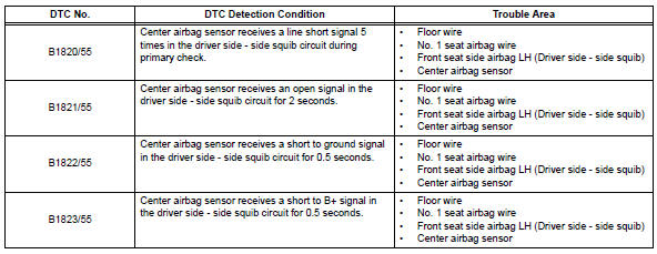
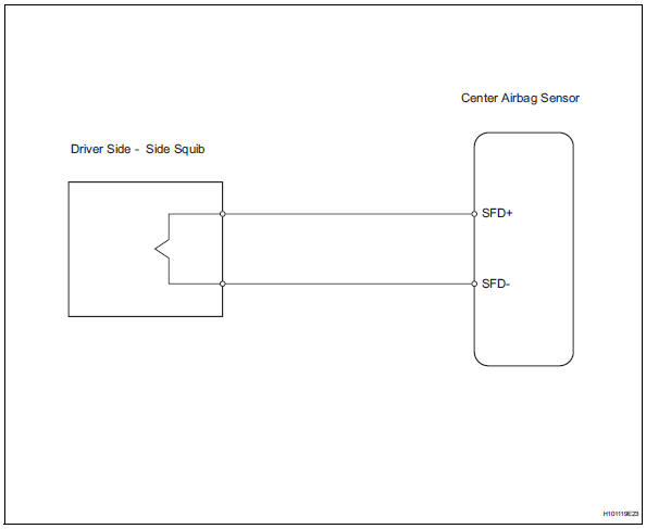
The driver side - side squib circuit consists of the center airbag sensor and the front seat side airbag lh.
This circuit instructs the srs to deploy when the deployment conditions are met.
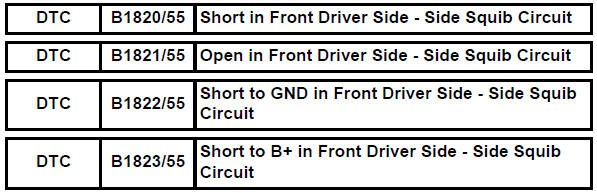
These dtcs are recorded when a malfunction is detected in the driver side - side squib circuit.
Wiring diagram
Inspection procedure
Hint:
- Perform the simulation method by selecting the "check mode" (signal check) with the intelligent tester (see page rs-52).
- After selecting the "check mode" (signal check), perform the simulation method by wiggling each connector of the airbag system or driving the vehicle on a city or rough road (see page rs-52).
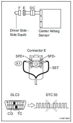
- Check front seat side airbag assembly lh (driver side - side squib)
- Turn the ignition switch off.
- Disconnect the cable from the negative (-) battery terminal, and wait for at least 90 seconds.
- Disconnect the connector from the front seat side airbag lh.
- Connect the black wire side of sst to connector e.
Caution:
Never connect a tester to the front seat side airbag lh (driver side - side squib) for measurement, as this may lead to a serious injury due to airbag deployment.
Notice:
- Do not forcibly insert sst into the terminals of the connector when connecting.
- Insert sst straight into the terminals of the connector
Sst 09843-18060
- Connect the cable to the negative (-) battery terminal, and wait for at least 2 seconds.
- Turn the ignition switch on, and wait for at least 60 seconds.
- Clear the dtcs (see page rs-49).
- Turn the ignition switch off
- Turn the ignition switch on, and wait for at least 60 seconds.
- Check the dtcs (see page rs-49).
Ok: dtc b1820, b1821, b1822, b1823 or 55 is not output.
Hint:
Dtcs other than dtc b1820, b1821, b1822, b1823 or 55 may be output at this time, but they are not related to this check.

- Check connector
- Turn the ignition switch off.
- Disconnect the cable from the negative (-) battery terminal, and wait for at least 90 seconds.
- Disconnect sst from the no. 1 Seat airbag wire.
- Check that the floor wire connectors (on the driver side - side squib) are not damaged.
Ok: lock button is not disengaged, and claw of lock is not deformed or damaged.

- Check floor wire (driver side - side squib circuit)
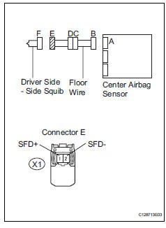
- Disconnect the connector from the center airbag sensor.
- Connect the cable to the negative (-) battery terminal, and wait for at least 2 seconds.
- Turn the ignition switch on.
- Measure the voltage of the wire harness side connector.
Standard voltage 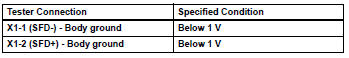
- Turn the ignition switch off.
- Disconnect the cable from the negative (-) battery terminal, and wait for at least 90 seconds.
- Measure the resistance of the wire harness side connector.
Standard resistance 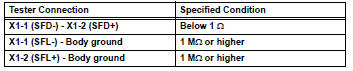
- Release the activation prevention mechanism built into connector b (see page rs-37).
- Measure the resistance of the wire harness side connector
Standard resistance 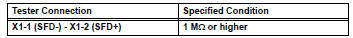

- Check no. 1 Seat airbag wire
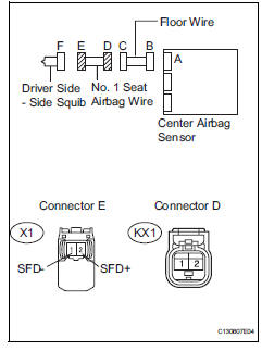
- Disconnect the no. 1 Seat airbag wire connector from the floor wire.
- Connect the cable to the negative (-) battery terminal, and wait for at least 2 seconds.
- Turn the ignition switch on.
- Measure the voltage of the wire harness side connector.
Standard voltage 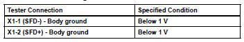
- Turn the ignition switch off.
- Disconnect the cable from the negative (-) battery terminal, and wait for at least 90 seconds.
- Measure the resistance of the wire harness side connector.
Standard resistance 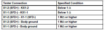

Repair or replace floor wire
 Short in front passenger side squib 2nd step circuit
Description
The front passenger side squib 2nd step circuit consists of the center airbag
sensor and the front
passenger airbag.
The circuit instructs the srs to deploy when the deployment ...
 Short in front passenger side - side squib circuit
Description
The front passenger side - side squib circuit consists of the center airbag
sensor and the front seat side
airbag rh.
The circuit instructs the srs to deploy when the deployment ...
Other materials:
Installation
Hint:
A bolt without a torque specification is shown in the standard
bolt chart (see page ss-2).
Install front seat inner belt assembly (for power seat)
Install the front seat inner belt assembly with the
nut.
Torque: 42 n*m (428 kgf*cm, 31 ft.*Lbf)
Notice:
Do not overlap the ...
Alarm
The alarm uses light and
sound to give an alert when
an intrusion is detected.
The alarm is triggered in the
following situations when
the alarm is set:
Vehicles without smart key
system: A locked door is
unlocked or opened in any
way other than using the
wireless remote control or
key. (The ...
Installation
Install starter assembly
Install the starter with the 2 bolts.
Torque: 37 n*m (377 kgf*cm, 27 ft.*Lbf)
Connect the starter connector.
Install the terminal nut and cover the nut with the
cap.
Torque: 9.8 N*m (100 kgf*cm, 7 ft.*Lbf)
Install battery bracket reinfor ...
