Toyota RAV4 (XA40) 2013-2018 Service Manual: Solar sensor (for automatic air conditioning system)
Components
Removal
- Disconnect cable from negative battery terminal
Caution:
Wait at least 90 seconds after disconnecting the cable from the negative (-) battery terminal to prevent airbag and seat belt pretensioner activation.
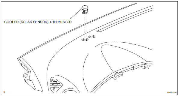
- Remove solar sensor
- Using a screwdriver, pull out the solar sensor, then disconnect the connector.
Hint:
Tape the screwdriver tip before use.
Inspection
- Inspect solar sensor
- Using an ohmmeter, connect the positive lead to terminal 2 and the negative lead to terminal 1, then measure the resistance between the terminals.
Standard resistance 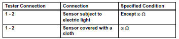
Notice:
The connection procedure for using a digital tester such as a toyota electrical tester is shown above. When using an analog tester, connect the positive (+) lead to terminal 1 and the negative (-) lead to terminal 2 of the a/c solar sensor.
Hint:
- As the inspection light is moved away from the sensor, the voltage increases.
- Use an incandescent lamp for inspection. Bring it within 30 cm (11.8 In.) Of the a/c solar sensor.
If the result is not as specified, replace the solar sensor.
Installation
- Install solar sensor
- Connect the connector, and then push in the solar sensor.
- Connect cable to negative battery terminal
- Check srs warning light
- Check the srs warning light (see page rs-37).
 Evaporator temperatur sensor
Removal
Remove air conditioning unit
Remove the air conditioning radiator (see page ac-
185).
Remove evaporator temperature sensor
(see page ac-193)
Inspection
Inspect evapo ...
 Heater relay
On-vehicle inspection
Inspect relay (marking: htr)
Measure the resistance of the htr relay.
Standard resistance
If the result is not as specified, replace the relay. ...
Other materials:
Downhill assist control indicator light does not come on
Description
Refer to the description of "downhill assist control indicator light remains
on" (see page bc-156).
Wiring diagram
Refer to the downhill assist control indicator light circuit (see page
bc-157).
Inspection procedure
Check can communication system
Check if the ...
Warning lights and indicators
The warning lights and indicators on the instrument cluster and
center panel inform the driver of the status of the vehicle’s various
systems.
For the purpose of explanation, the following illustration displays
all warning lights and indicators illuminated.
Instrument cluster
Some indi ...
Valve clearance
Adjustment
Disconnect cable from negative battery
terminal
Caution:
Wait at least 90 seconds after disconnecting the
cable from the negative (-) battery terminal to
prevent airbag and seat belt pretensioner activation.
Remove front wheel rh
Remove no. 1 Engine under cover
Remove ...
