Toyota RAV4 (XA40) 2013-2018 Service Manual: Symptom confirmation and diagnostic trouble code
Hint:
The diagnostic system in the rav4 has various functions.
- The first function is the diagnostic trouble code (dtc) check. A dtc is a code stored in the ecu memory whenever a malfunction in the signal circuits to the ecu occurs. In a dtc check, a previous malfunction's dtc can be checked by a technician during troubleshooting.
- Another function is the input signal check, which
checks if the signals from various switches are sent to
the ecu correctly.
By using these functions, the problem areas can be narrowed down and troubleshooting is more effective.
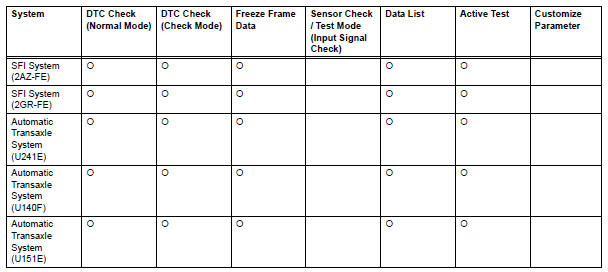
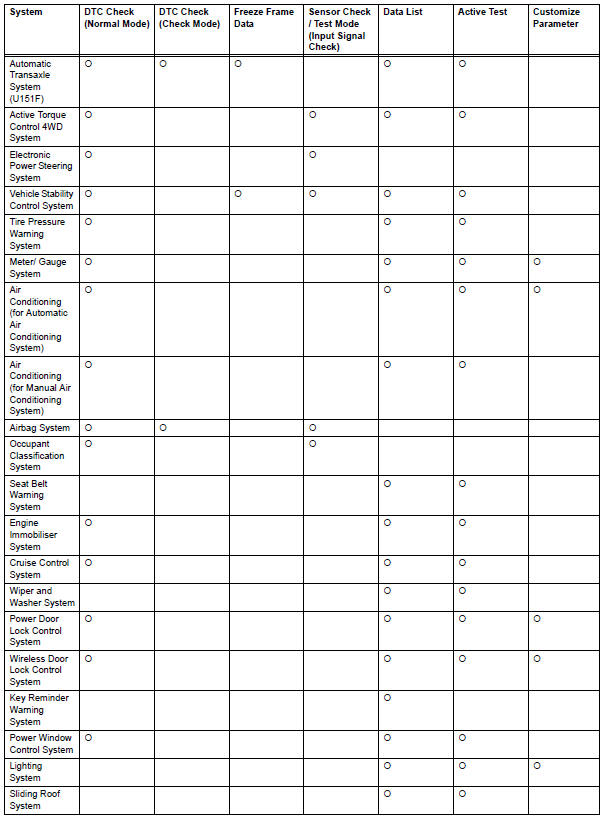
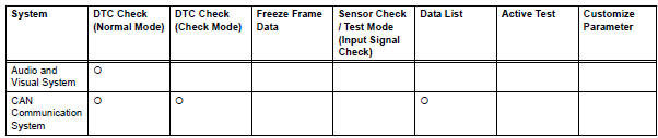
Diagnostic functions are incorporated in the following system in the rav4.
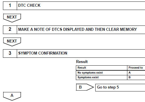
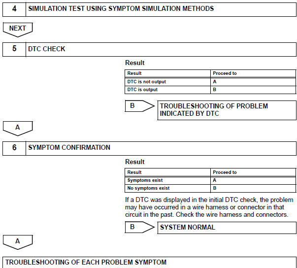
- In the dtc check, it is very important to determine whether the problem indicated by the dtc is either: 1) still occurring, or 2) occurred in the past but has since returned to normal. In addition, the dtc should be compared to the problem symptom to see if they are related. For this reason, dtcs should be checked before and after confirmation of symptoms (i.E., Whether or not problem symptoms exist) to determine current system conditions, as shown in the flowchart below.
- Never skip the dtc check. Failing to check dtcs may, depending on the case, result in unnecessary troubleshooting for systems operating normally or lead to repairs not related to the problem. Follow the procedures listed in the flowchart in the correct order.
- The following flowchart shows how to proceed with troubleshooting using the dtc check. Directions from the flowchart will indicate how to proceed either to dtc troubleshooting or to the troubleshooting of each problem symptom.
The problem is still occurring in a place other than the diagnostic circuit (the dtc displayed first is either for a past problem or a secondary problem).
 Customer problem analysis
Hint:
In troubleshooting, confirm that the problem symptoms
have been accurately identified. Preconceptions should be
discarded in order to make an accurate judgment. To
clearly understand w ...
 Symptom simulation
Hint:
The most difficult case in troubleshooting is when no
problem symptoms occur. In such a case, a thorough
problem analysis must be carried out. A simulation of the
same or similar conditions ...
Other materials:
Exhaust pipe
Components
Removal
Disconnect cable from negative battery terminal
Caution:
Wait at least 90 seconds after disconnecting the
cable from the negative (-) battery terminal to
prevent airbag and seat belt pretensioner activation.
Remove heated oxygen sensor (for bank 1
sensor 2) (s ...
Precaution
Before disassembling the differential assembly,
thoroughly clean it by removing any sand, mud or
foreign matter. This will help prevent contamination
during disassembly and reassembly.
When removing the rear differential carrier cover or
any other light alloy part, do not pry it off wit ...
Downhill assist control indicator light does not come on
Description
Refer to the description of "downhill assist control indicator light remains
on" (see page bc-156).
Wiring diagram
Refer to the downhill assist control indicator light circuit (see page
bc-157).
Inspection procedure
Check can communication system
Check if the ...
