Toyota RAV4 (XA40) 2013-2018 Service Manual: Tc and cg terminal circuit
Description
Dtc output mode is set by connecting terminals tc and cg of the dlc3.
The dtcs are displayed by blinking the srs warning light.
Hint:
- Make sure that dtc b1281 has not been output. If dtc b1281 has been output, refer to the multiplex communication system.
- When each warning light keeps blinking, a ground short in the wiring of terminal tc of the dlc3 or an internal ground short in each ecu is suspected.
Wiring diagram
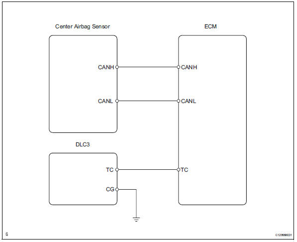
Inspection procedure
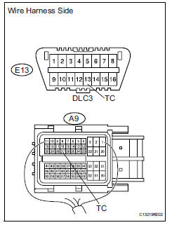
- Check wire harness (dlc3 - ecm)
- Turn the ignition switch off.
- Disconnect the a9 connectors from the center airbag sensor .
- Measure the resistance of the wire harness side connectors.
Standard resistance 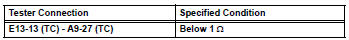

- Check wire harness (cg of dlc3 - body ground)
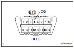
- Measure the resistance of the wire harness side connectors.
Standard resistance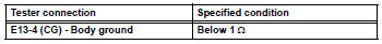

- Check wire harness (tc of ecm)
- Measure the resistance of the wire harness side connector.
Standard resistance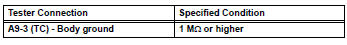

- Replace ecm
- Replace the ecm.
- Check the dtc of the ecm (see page es-35).
Result 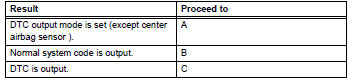

Repair or replace wire harness or each ecu
 Srs warning light does not come on
Description
The srs warning light is located on the combination meter.
When the srs is normal, the srs warning light comes on for approximately 6
seconds after the ignition
switch is turned fro ...

Other materials:
Catalyst monitor (active air-fuel ratio control type)
Preconditions
The monitor will not run unless:
The mil is off.
Drive pattern
Connect the intelligent tester to the dlc3.
Turn the ignition switch on.
Turn the tester on.
Clear dtcs (if set) (see page es-35).
Start the engine and warm it up.
Drive the vehicle at be ...
Oil filter
Components
Replacement
Caution:
Prolonged and repeated contact with engine oil will
cause the loss of natural oils from the skin, leading to
dryness, irritation and dermatitis. In addition, used
engine oil contains potentially harmful contaminants
which may cause skin cancer.
Pre ...
Floor shift assembly
Components
Removal
Disconnect cable from negative battery
terminal
Caution:
Wait at least 90 seconds after disconnecting the
cable from the negative (-) battery terminal to
prevent airbag and seat belt pretensioner activation.
Remove shift lever knob sub-assembly
Remove re ...
