
Toyota RAV4 (XA40) 2013-2018 Owners Manual: Automatic air conditioning system
Air outlets and fan speed are automatically adjusted according to the temperature setting.
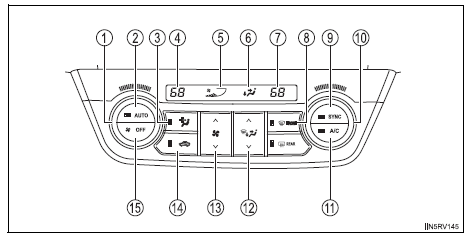
- Driver’s side temperature control dial
- Automatic mode button
- Micro dust and pollen filter mode button
- Driver’s side temperature setting display
- Fan speed display
- Air outlet display
- Passenger’s side temperature setting display
- Windshield defogger button
- Simultaneous mode button
- Passenger’s side temperature control dial
- Cooling and dehumidification function on/off button
- Air outlet selector button
- Fan speed control button
- Outside air or recirculated air mode button
- Off button
- Using the automatic air conditioning system
- Adjusting the settings manually
- Defogging the windshield
- Micro dust and pollen filter mode button
- Adjusting the position of and opening and closing the air outlets
 Air outlets and air flow
Upper body
Upper body and feet
Feet
Feet and windshield
Switching between outside air and recirculated air modes
Press .
The mode switches between outside air mode (indica ...
 Using the automatic air conditioning system
Press .
The dehumidification function begins to operate. Air outlets and fan speed
are automatically adjusted according to the temperature setting and
humidity.
Turn clockwis ...
Other materials:
Driving assist systems
To help enhance driving safety and performance, the following
systems operate automatically in response to various driving
situations. Be aware, however, that these systems are supplementary
and should not be relied upon too heavily when operating
the vehicle.
Abs (anti-lock brake system)
Help ...
Rear airbag sensor
Components
On-vehicle inspection
Check rear airbag sensor (vehicle not
involved in collision)
Perform a diagnostic system check (see page rs-
49).
Check rear airbag sensor (vehicle
involved in collision and airbag has not
deployed)
Perform a diagnostic system check ...
Problem symptoms table (2006/01- )
Hint:
Use the table below to help determine the cause of the
problem symptom. The potential causes of the symptoms are
listed in order of probability in the "suspected area" column
of the table. Check each symptom by checking the suspected
areas in the order they are listed. Replace p ...
