Toyota RAV4 (XA40) 2013-2018 Service Manual: Tc and cg terminal circuit
Description
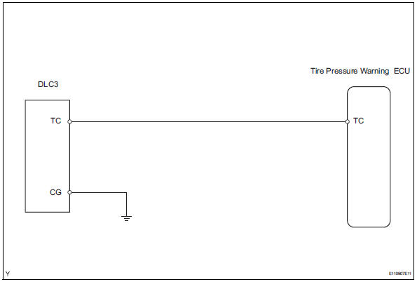
Dtc output mode is set by connecting terminals 13 (tc) and 4 (cg) of the dlc3. The dtcs are indicated by the blinking of the tire pressure warning light.
Wiring diagram
Hint:
When each warning light continues blinking, a ground short in the wiring of terminal tc of the dlc3 or an internal ground short in each ecu may have occurred.
Inspection procedure
Notice:
It is necessary to register an id code after replacing the tire pressure monitor valve and/or the tire pressure warning ecu (see page tw-9).
- Check wire harness (dlc3 - ecu)
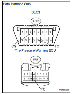
- Disconnect the e13 dlc3 connector.
- Disconnect the e56 ecu connector.
- Measure the resistance of the wire harness side connectors.
Standard resistance 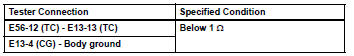

Proceed to next circuit inspection shown in problem symptoms table

 Removal
Disconnect cable from negative battery
terminal
Caution:
Wait at least 90 seconds after disconnecting the
cable from the negative (-) battery terminal to
prevent airbag and seat belt preten ...
Other materials:
Registration
Notice:
The vehicle identification number (vin) must be input
into the replacement ecm.
Hint:
The vin is a 17-digit alphanumeric number. The intelligent
tester is required to register the vin.
Description
This registration section consists of 3 parts: input
instructions, read vin and wr ...
Vacuum switching valve
Components
Removal
Disconnect cable from negative battery
terminal
Caution:
Wait at least 90 seconds after disconnecting the
cable from the negative (-) battery terminal to
prevent airbag and seat belt pretensioner activation.
Remove purge vsv
Disconnect the purge vsv ...
Exhaust pipe
Installation
Install front exhaust pipe assembly
Using a vernier caliper, measure the free length of
the compression spring.
Minimum length:
41.5 Mm (1.634 In.)
If the length is less than the minimum, replace the
compression spring.
Install a new gasket by hand so that its ...
