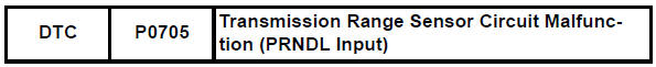
Toyota RAV4 (XA40) 2013-2018 Service Manual: Transmission range sensor circuit malfunction (prndl input)
Description
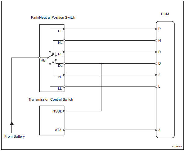
The park/neutral position (pnp) switch detects the shift lever position and sends signals to the ecm.
Monitor description
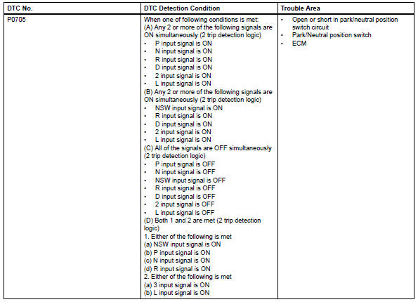
These dtcs indicate a problem with the park/neutral position switch and the wire harness in the park/ neutral position switch circuit.
The park/neutral position switch detects the shift lever position and sends a signal to the ecm.
For security, the park/neutral position switch detects the shift lever position so that the engine can be started only when the shift lever is on p or n.
The park/neutral position switch sends a signal to the ecm according to the shift lever position (r, d, 3, 2 or l).
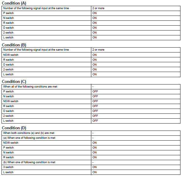
The ecm determines that there is a problem with the switch or related parts if it receives more than 1 position signal simultaneously. The ecm will illuminate the mil and store the dtc.
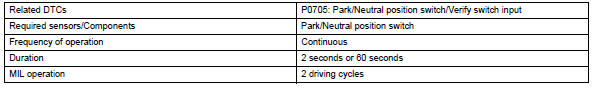
Monitor strategy
![]()
Typical enabling conditions

Typical malfunction thresholds
Component operating range
![]()
Wiring diagram
Inspection procedure
Hint:
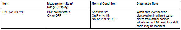
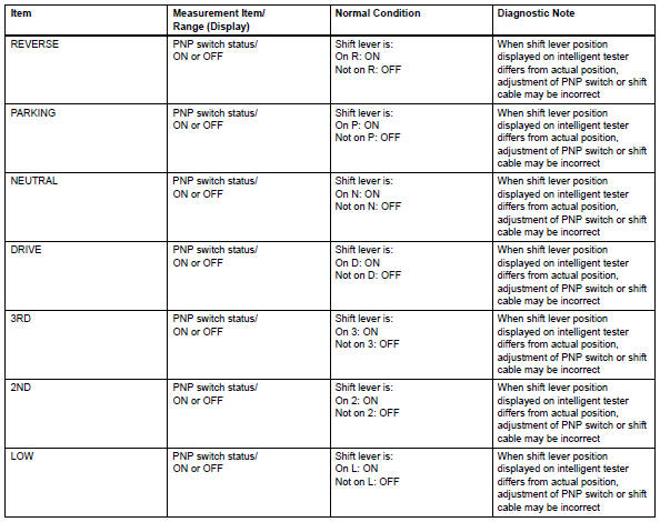
Using the intelligent tester's data list allows switch, sensor, actuator and other item values to be read without removing any parts. Reading the data list early in troubleshooting is one way to save time.
Notice:
In the table below, the values listed under "normal condition" are reference values. Do not depend solely on these reference values when deciding whether a part is faulty or not.
- Warm up the engine.
- Turn the ignition switch off.
- Connect the intelligent tester to the can vim. Then connect the can vim to the dlc3.
- Turn the ignition switch on and turn the tester on.
- Enter the following menus: diagnosis / enhanced obd ii / data list.
- Follow the instructions on the tester and read the data list.
- Check wire harness (park/neutral position switch - battery)
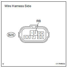
- Disconnect the b26 park/neutral position switch connector.
- Turn the ignition switch on.
- Measure the voltage.
Standard voltage 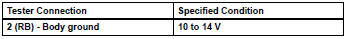


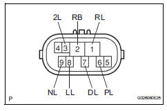
- Inspect park/neutral position switch
- Disconnect the b26 park/neutral position switch connector.
- Measure the resistance of the park/neutral position switch when the shift lever is moved to each position.
Standard resistance 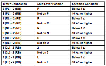

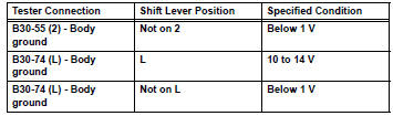
- Check wire harness (ecm - battery and body ground)
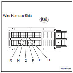
- Disconnect the b30 ecm connector.
- Turn the ignition switch on.
- Measure the voltage of the wire harness side connector.
Standard voltage 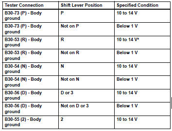
Hint:
*: The voltage will drop slightly due to the illumination of the back-up light.

- Check wire harness (park/neutral position switch - transmission control switch)
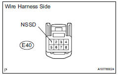
- Disconnect the e40 switch connector.
- Turn the ignition switch on.
- Measure the voltage when the shift lever is moved to each position.
Standard voltage 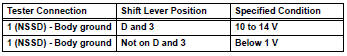

- Inspect transmission control switch
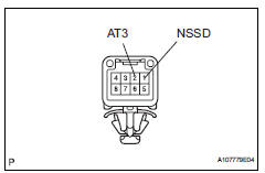
- Disconnect the e40 switch connector.
- Measure the resistance of the switch when the shift lever is moved to each position.
Standard resistance 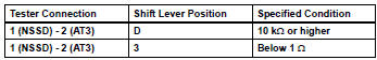

- Check wire harness (transmission control switch - battery and body ground)
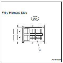
- Disconnect the a9 ecm connector.
- Turn the ignition switch on.
- Measure the voltage of the wire harness side connector.
Standard voltage 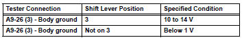
Hint:
*: The voltage will drop slightly due to the illumination of the back-up light.

 Diagnostic trouble code chart
If a dtc is displayed during the dtc check, check the circuit
listed in the table below and proceed to the page given.
Hint:
*1: "Comes on" means the malfunction indicator lamp
(mil) ...
 Transmission fluid temperature sensor "A" circuit
Description
The automatic transmission fluid (atf) temperature sensor converts the atf
temperature into a
resistance value which is input into the ecm.
The ecm applies a voltage to the temp ...
Other materials:
Fog light switch
The fog lights offer
improved visibility in difficult
driving conditions,
such as in rain and fog.
Operating procedure
*1 or
*2 Turns the
fog lights off
Turns the fog lights on
*1:For the U.S.A.
*2:For Canada
â– Fog lights can be used when
The headlights are on in low beam. ...
Differential oil seal
Components
Replacement
Replace transaxle housing oil seal lh
Drain the automatic transaxle fluid.
Remove the drain plug and gasket, and drain
atf.
Install a new gasket and drain plug.
Torque: 47 n*m (479 kgf*cm, 35 ft.*Lbf)
Remove the front drive shaft lh (see pag ...
Display contents
Following information is displayed
on the multi-information
display.
Content display area (left)
Content display area (center)
Content display area (right)
Driving support system information
display area
When driving information support
system is displayed on the content
display area, the sy ...
