Toyota RAV4 (XA40) 2013-2018 Service Manual: Diagnostic trouble code chart
If a dtc is displayed during the dtc check, check the circuit listed in the table below and proceed to the page given.
Hint:
- *1: "Comes on" means the malfunction indicator lamp (mil) illuminates.
- *2: "Dtc stored" means the ecm memorizes the malfunction code if the ecm detects the dtc detection condition.
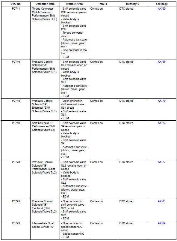
- These dtcs may be output when the clutch, brake, gear components, etc., Inside the automatic transaxle are damaged.
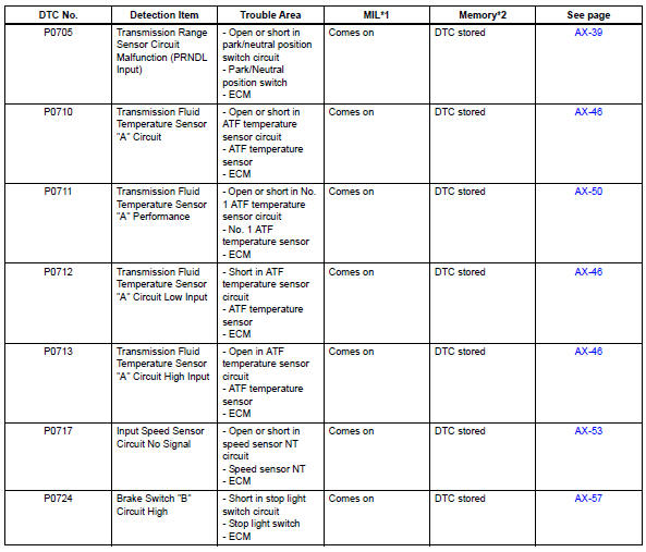
- Transmission range sensor circuit malfunction (prndl input)
- Transmission fluid temperature sensor "A" circuit
- Transmission fluid temperature sensor "A" performance
- Input speed sensor circuit no signal
- Brake switch "B" circuit high
- Torque converter clutch solenoid performance (shift solenoid valve dsl)
- Pressure control solenoid "A " performance (shift solenoid valve sl1)
- Pressure control solenoid "A" electrical (shift solenoid valve sl1)
- Shift solenoid "d" performance (shift solenoid valve s4)
- Pressure control solenoid "B" performance (shift solenoid valve sl2)
- Pressure control solenoid "b" electrical (shift solenoid valve sl2)
- Intermediate shaft speed sensor "A"
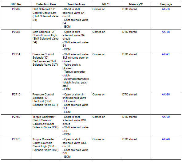
- Shift solenoid "d" control circuit
- Pressure control solenoid "d" performance (shift solenoid valve slt)
- Pressure control solenoid "d" electrical (shift solenoid valve slt)
- Torque converter clutch solenoid circuit
 Data list / active test
Read data list
Hint:
Using the intelligent tester's data list allows switch,
sensor, actuator, and other item values to be read
without removing any parts. Reading the data list
early in tro ...
 Transmission range sensor circuit malfunction (prndl input)
Description
The park/neutral position (pnp) switch detects the shift lever position and
sends signals to the ecm.
Monitor description
These dtcs indicate a problem with the park/neutral p ...
Other materials:
Hitch
Trailer hitch assemblies have different weight capacities. Toyota recommends
the use of toyota hitch/bracket for your vehicle. For details,
contact your toyota dealer.
If you wish to install a trailer hitch, contact your toyota dealer.
Use only a hitch that conforms to the gross trailer weig ...
Transmission control cable assembly
Replacement
Remove rear console box sub-assembly
Remove the console box (see page ip-20).
Disconnect cable from negative battery
terminal
Caution:
Wait at least 90 seconds after disconnecting the
cable from the negative (-) battery terminal to
prevent airbag and seat belt pre ...
Rear occupant classification sensor lh collision detection
Description
Dtc b1787 is output when the occupant classification ecu receives a collision
detection signal sent by
the rear occupant classification sensor lh when an accident occurs.
Dtc b1787 is also output when the front seat assembly rh is subjected to a
strong impact, even if an
actua ...
