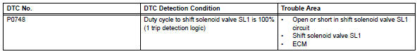
Toyota RAV4 (XA40) 2013-2018 Service Manual: Pressure control solenoid "A" electrical (shift solenoid valve sl1)
Description
Shifting from 1st to o/d is performed in combination with the on and off operation of the shift solenoid valves sl1 and sl2, which are controlled by the ecm. If an open or short circuit occurs in any of the shift solenoid valves, the ecm controls the remaining normal shift solenoid valves to allow the vehicle to be operated safely (see page ax-31).
Monitor description
This dtc indicates an open or short in the shift solenoid valve sl1 circuit. The ecm commands gear shifts by turning the shift solenoid valves on/off. When there is an open or short circuit in any shift solenoid valve circuit, the ecm detects the problem, illuminates the mil and stores the dtc. Also, the ecm performs the fail-safe function and turns the other normal shift solenoid valves on/off. In case of an open or short circuit, the ecm stops sending current to the circuit (see page ax-31).
Monitor strategy
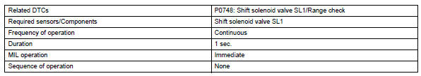
Typical enabling conditions
Typical malfunction thresholds
![]()
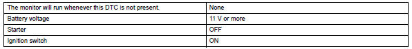
Component operating range
![]()
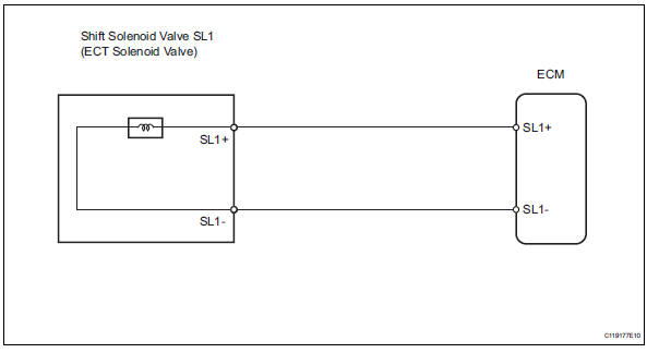
Wiring diagram
Inspection procedure
- Inspect transmission wire (shift solenoid valve sl1)
- Disconnect the b27 wire connector.
- Measure the resistance of the transmission wire.
Standard resistance 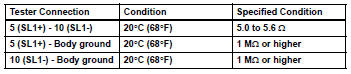

- Check wire harness (transmission wire - ecm)
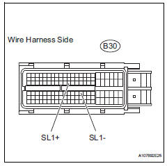
- Disconnect the b30 ecm connector.
- Measure the resistance of the wire harness side connector.
Standard resistance 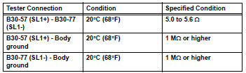

Replace ecm
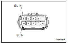
- Inspect shift solenoid valve sl1
- Remove the shift solenoid valve sl1.
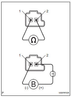
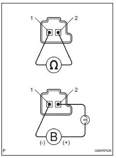
- Measure the resistance of the solenoid valve.
Standard resistance: 5.0 To 5.6 Ùat 20°c (68°f)
- Connect the battery's positive (+) lead with a 21 w bulb to terminal 2 and the negative (-) lead to terminal 1 of the solenoid valve connector. Then check that the valve moves and makes an operating noise.
Ok: valve moves and makes operating noise.

Repair or replace transmission wire
- Check wire harness (transmission wire - ecm)
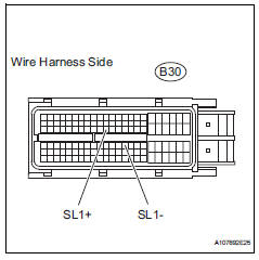
- Disconnect the b30 ecm connector.
- Measure the resistance of the wire harness side connector.
Standard resistance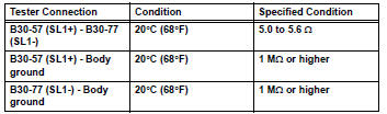

Replace ecm
- Inspect shift solenoid valve sl1
- Remove the shift solenoid valve sl1.
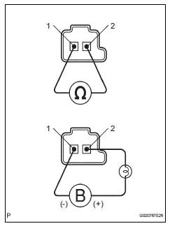
- Measure the resistance of the solenoid valve.
Standard resistance: 5.0 To 5.6 Ùat 20°c (68°f)
- Connect the battery's positive (+) lead with a 21 w bulb to terminal 2 and the negative (-) lead to terminal 1 of the solenoid valve connector. Then check that the valve moves and makes an operating noise.
Ok: valve moves and makes operating noise.


Repair or replace transmission wire
 Pressure control solenoid "A " performance (shift solenoid valve sl1)
Description
The ecm uses signals from the vehicle speed sensor to detect the actual gear
position (1st, 2nd, 3rd or
o/d gear).
Then the ecm compares the actual gear with the shift schedule in t ...
 Shift solenoid "d" performance (shift solenoid valve s4)
System description
The ecm uses signals from the output shaft speed sensor and input speed
sensor to detect the actual
gear position (1st, 2nd, 3rd or o/d gear).
Then the ecm compares the a ...
Other materials:
Terminals of ecu
Check tire pressure warning ecu
Disconnect the e56 ecu connector.
Measure the voltage and resistance of the wire
harness side connector.
If the result is not as specified, there may be a
malfunction on the wire harness side.
Reconnect the e56 ecu connector.
Measure the ...
Evaporator temperature sensor circuit
Description
The no. 1 Cooler thermistor (evaporator temperature sensor) is installed on
the evaporator in the air
conditioning unit to detect the temperature of the cooled air that has passed
through the evaporator and to
control the air conditioner. It sends signals to the air conditioni ...
Removal
Disconnect cable from negative battery
terminal
Caution:
Wait at least 90 seconds after disconnecting the
cable from the negative (-) battery terminal to
prevent airbag and seat belt pretensioner activation.
Remove no. 1 Engine cover (see page es-410)
Remove air cleaner cap (see pag ...
