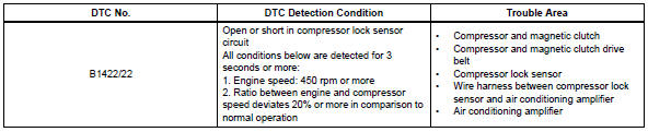
Toyota RAV4 (XA40) 2013-2018 Service Manual: Compressor lock sensor circuit
![]()
Description
This sensor sends 1 pulse per engine revolution to the air conditioning amplifier. If the ratio of the compressor speed divided by the engine speed is smaller than a predetermined value, the air conditioning amplifier turns the compressor off, and the indicator blinks at approximately 1 second intervals.
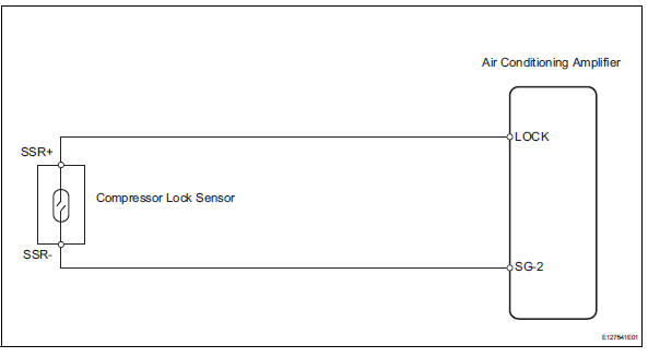
Wiring diagram
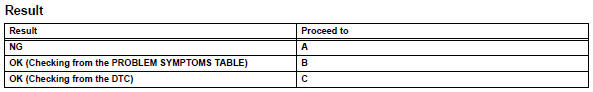
Inspection procedure
- Check air conditioning amplifier (lock signal)
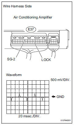
- Remove the air conditioning amplifier with its connectors still connected.
- Check the waveform of the amplifier connector.
Ok:
waveform is as shown in the illustration.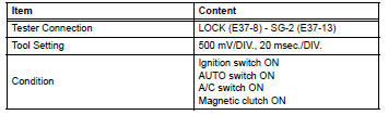

- Inspect compressor lock sensor
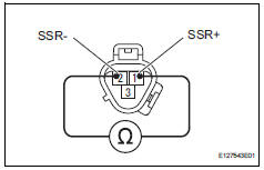
- Disconnect the b47 compressor lock sensor connector.
- Measure the resistance of the sensor.
Standard resistance

- Check wire harness (compressor lock sensor - air conditioning amplifier)
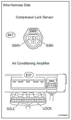
- Disconnect the b47 compressor lock sensor connector.
- Disconnect the e37 amplifier connector.
- Measure the resistance of the wire harness side connectors.
Standard resistance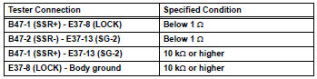

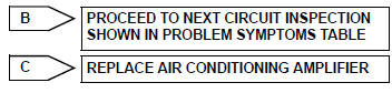
Replace air conditioning amplifier
 Solar sensor circuit (passenger side)
Description
The solar sensor, which is installed on the upper side of the instrument
panel, detects sunlight and
controls the air conditioning auto mode. The output voltage from the solar
se ...
 Pressure sensor circuit
Description
This dtc is output when the refrigerant pressure is either extremely low
(0.19 Mpa [2.0 Kgf/cm2, 28 psi]
or less) or extremely high (3.14 Mpa [32.0 Kgf/cm2, 455 psi] or more). The ...
Other materials:
Knock sensor 1 circuit
Description
Flat type knock sensors (non-resonant type) have structures that can detect
vibrations over a wide band
of frequencies: between approximately 6 khz and 15 khz.
A knock sensor is fitted onto the engine block to detect engine knocking.
The knock sensor contains a piezoelectri ...
Data list / active test (2005/11-2006/01)
Read data list
Hint:
Using the intelligent tester's data list allows switch,
sensor, actuator and other item values to be read without
removing any parts. Reading the data list early in
troubleshooting is one way to save time.
Connect the intelligent tester (with can vim) to the
...
Gauges and meters (with 7- inch multi-information
display)
The meters display various drive information.
Meter display
The display of the speedometer can be selected from two types,
analog or digital.
Analog speedometer
The units used on the meter and display may differ depending on the target
region.
Tachometer
Displays the engine speed in revolutions ...
