Toyota RAV4 (XA40) 2013-2018 Service Manual: Removal
- Drain differential oil
- Remove rear wheel
- Remove tailpipe assembly
- Remove the tailpipe (see page ex-2).
- Remove center exhaust pipe assembly
- Remove the center pipe (see page ex-2).
- Remove propeller with center bearing shaft assembly (see page pr-3)
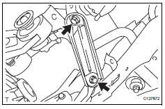
- Remove rear suspension member brace lh
- Remove the 2 bolts and brace from the suspension member.
- Remove rear suspension member brace r
h
Hint:
Use the same procedures described for the lh side.
- Remove rear differential carrier subassembly
- Disconnect the harness clamp.
- Remove the breather tube.
- Disconnect the connector.
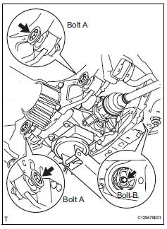
- Support the rear differential carrier with a transmission jack or equivalent.
- Fix the nuts in place and remove bolt a, bolt b and bolt c.
Notice:
Do not loosen the nuts. Loosen the bolts.
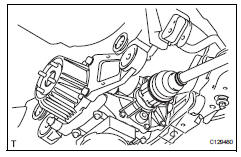
- Slowly lower the jack and then tilt the rear differential carrier.
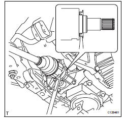
- Set the tip of the tire lever to the position on the rear
drive shaft inboard joint shown in the illustration.
Then, using the ribbed part of the rear differential carrier as a fulcrum, disconnect the left and right rear drive shafts.
Notice:
Do not scratch the rear drive shaft dust cover.
- Remove rear differential no. 1 And no. 2 Support
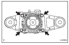
- Remove the 4 bolts and differential no. 1 And no. 2 Supports from the differential carrier.
- Remove rear differential support
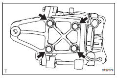
- Remove the 4 bolts and differential support from the differential carrier.
 Rear differential carrier assembly
Components
...
 Disassembly
Fix differential carrier sub-assembly
Fix the rear differential carrier in place with the
overhaul attachment.
Remove stud bolt
Remove the 4 stud bolts from the transmission
c ...
Other materials:
Removal
Remove radiator support opening cover
Remove front wheel rh
Remove front fender apron rh
Remove front suspension member
reinforcement rh
Remove the 4 bolts and reinforcement rh.
Remove fan and generator v belt
Using sst and 19 mm socket wrench, loosen the vribbed
belt ...
Removal
Caution:
Be sure to read the precautionary notices concerning the
srs airbag system before servicing it (see page rs-1).
Disconnect cable from negative battery
terminal
Caution:
Wait at least 90 seconds after disconnecting the
cable from the negative (-) battery terminal to
prevent air ...
Idle control system malfunction
Description
The idling speed is controlled by the etcs (electronic throttle control
system). The etcs is comprised
of: 1) the one valve type throttle body; 2) the throttle actuator, which
operates the throttle valve; 3) the
throttle position (tp) sensor, which detects the opening angle of ...
