Toyota RAV4 (XA40) 2013-2018 Service Manual: Input speed sensor circuit no signal
![]()
Description
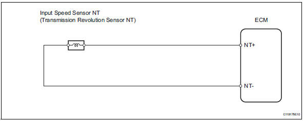
This sensor detects the rotation speed of the turbine, which shows the input revolution of the transaxle. By comparing the input speed signal (nt) with the counter gear speed sensor signal (nc), the ecm detects the shift timing of the gears and controls the engine torque and hydraulic pressure according to various conditions. As a result, smooth gear shifting is achieved.
Monitor description
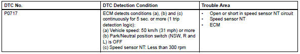
This dtc indicates that a pulse is not output from the speed sensor nt (input speed sensor) or is output only a little. The nt terminal of the ecm detects the revolving signal from the speed sensor (nt) (input rpm). The ecm outputs a gear shift signal comparing the input speed sensor (nt) with the output speed sensor (nc).
While the vehicle is operating in the 2nd, 3rd or o/d gear position with the shift lever on d, if the input shaft revolution is less than 300 rpm*1 and the output shaft revolution is 1,000 rpm or more*2, the ecm detects the trouble, illuminates the mil and stores the dtc.
Hint:
*1: Pulse is not output or is irregularly output.
*2: The vehicle speed is approximately 50 km/h (31 mph) or more.
Monitor strategy
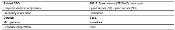
Typical enabling conditions
Typical malfunction thresholds
![]()
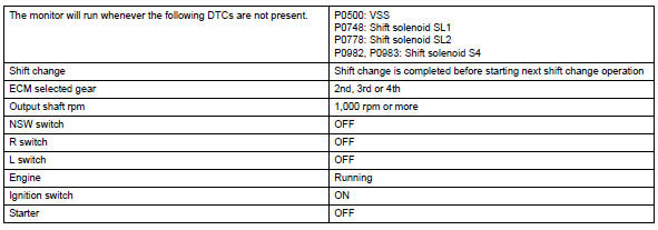
Component operating range
![]()
Wiring diagram
Inspection procedure
Hint:
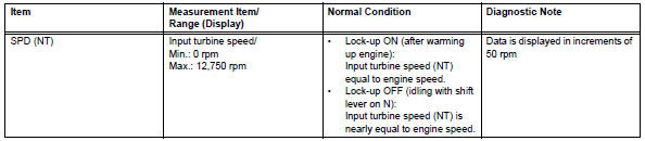
Using the intelligent tester's data list allows switch, sensor, actuator and other item values to be read without removing any parts. Reading the data list early in troubleshooting is one way to save time.
Notice:
In the table below, the values listed under "normal condition" are reference values. Do not depend solely on these reference values when deciding whether a part is faulty or not.
- Warm up the engine.
- Turn the ignition switch off.
- Connect the intelligent tester to the can vim. Then connect the can vim to the dlc3.
- Turn the ignition switch on and turn the tester on.
- Enter the following menus: diagnosis / enhanced obd ii / data list.
- Follow the instructions on the tester and read the data list.
Hint:
- Spd (nt) is always 0 rpm while driving: open or short in the sensor or circuit.
- Spd (nt) is always more than 0 rpm and less than 300 rpm while driving the vehicle at 50 km/h (31 mph) or more: sensor trouble, improper installation, or intermittent connection trouble of the circuit.
- Inspect speed sensor (installation)
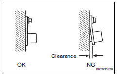
- Check the speed sensor nt installation.
Ok: installation bolt is tightened properly and there is no clearance between the sensor and transaxle case.

- Inspect speed sensor nt
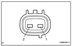
- Disconnect the b28 sensor connector from the transaxle.
- Measure the resistance of the sensor.
Standard resistance 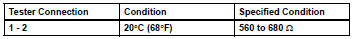


- Check wire harness (speed sensor - ecm)
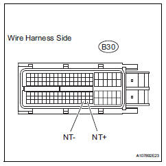
- Disconnect the b30 ecm connector.
- Measure the resistance of the wire harness side connector.
Standard resistance 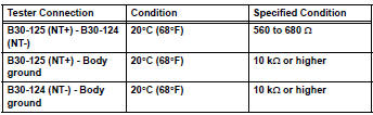

Replace ecm
 Transmission fluid temperature sensor "A" performance
Description
Refer to dtc p0710 (see page ax-46).
Monitor description
This dtc indicates that there is a problem with output from the atf
temperature sensor and that the
sensor itself is ...
 Brake switch "B" circuit high
Description
The purpose of this circuit is to prevent the engine from stalling while
driving in the lock-up condition when
the brakes are suddenly applied.
When the brake pedal is depressed ...
Other materials:
Air conditioning control assembly (for automatic air conditioning system)
Components
Removal
Disconnect cable from negative battery
terminal
Notice:
Wait at least 90 seconds after disconnecting the
cable from the negative (-) battery terminal to
prevent airbag and seat belt pretensioner activation.
Remove no. 2 Instrument cluster finish
panel center ...
Integration relay
On-vehicle inspection
Disconnect cable from negative battery
terminal
Caution:
Wait at least 90 seconds after disconnecting the
cable from the negative (-) battery terminal to
prevent airbag and seat belt pretensioner activation.
Inspect integration relay
Notice:
The efi relay ...
Cooling system
On-vehicle inspection
Check cooling system for leaks
Remove the radiator reservoir cap.
Caution:
To avoid the danger of being burned, do not
remove the radiator reservoir cap while the
engine and radiator are still hot. Thermal
expansion will cause hot engine coolant and
steam to b ...
