Toyota RAV4 (XA40) 2013-2018 Service Manual: Torque converter clutch solenoid circuit
Description
The shift solenoid valve dsl is turned on and off by signals from the ecm to control the hydraulic pressure acting on the lock-up relay valve, which then controls operation of the lock-up clutch.
Fail-safe function: if the ecm detects a malfunction, it turns the shift solenoid valve dsl off.
Monitor description
Torque converter lock-up is controlled by the ecm based on engine rpm, engine load, engine temperature, vehicle speed, transmission temperature, and shift position selection. The ecm determines the lock-up status of the torque converter by comparing the engine rpm (ne) to the input rpm (nt). The ecm calculates the actual transmission gear by comparing the input rpm (nt) to the output rpm (sp2).
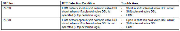
When conditions are appropriate, the ecm requests "lock-up" by applying control voltage to the shift solenoid valve dsl. When the shift solenoid valve dsl is opened, the shift solenoid valve dsl applies pressure to the lock-up relay valve and locks the torque converter clutch. If the ecm detects an open or short in the shift solenoid valve dsl circuit, the ecm interprets this as a fault in the shift solenoid valve dsl or its circuit. The ecm will illuminate the mil and store a dtc.
Monitor strategy
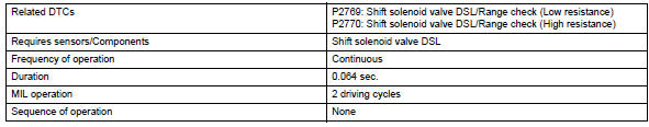
Typical enabling conditions
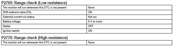
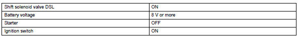
Typical malfunction thresholds
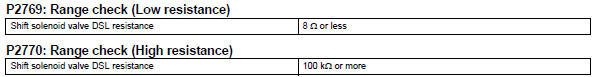
Component operating range
![]()
Wiring diagram
Refer to dtc p0741 (see page ax-62).
Inspection procedure
- Inspect transmission wire (shift solenoid valve dsl)
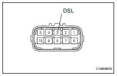
- Disconnect the b27 wire connector.
- Measure the resistance of the transmission wire.
Standard resistance 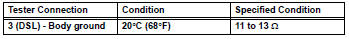

- Check wire harness (transmission wire - ecm)
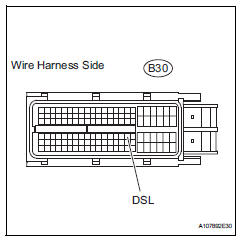
- Disconnect the b30 ecm connector.
- Measure the resistance of the wire harness side connector.
Standard resistance 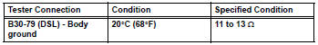

Replace ecm
- Inspect shift solenoid valve dsl
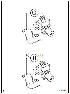
- Remove the shift solenoid valve dsl.
- Measure the resistance between the solenoid valve terminal and solenoid valve body.
Standard resistance:
11 to 13  at 20°c (68°f)
- Connect the battery's positive (+) lead to the terminal of the solenoid valve connector, and the negative (-) lead to the solenoid body. Then check that the valve moves and makes an operating noise.
Ok: valve moves and makes operating noise.


Repair or replace transmission wire
 Pressure control solenoid "d" electrical (shift solenoid valve slt)
Description
Refer to dtc p2714 (see page ax-91).
Monitor description
When an open or short in the shift solenoid valve slt circuit is detected,
the ecm interprets this as a fault.
The ...
 Automatic transaxle fluid
On-vehicle inspection
Check transaxle fluid level
Hint:
Drive the vehicle so that the engine and transaxle are at
normal operating temperature.
Fluid temperature:
70 to 80°c (158 to 176°f ...
Other materials:
Removal
Disconnect cable from negative battery
terminal
Caution:
Wait at least 90 seconds after disconnecting the
cable from the negative (-) battery terminal to
prevent airbag and seat belt pretensioner activation.
Remove no. 1 Engine cover (see page es-410)
Remove camshaft timing oil cont ...
Turning on the high beam headlights
With the headlights on, push
the lever away from you to turn
on the high beams.
Pull the lever toward you to the
center position to turn the high
beams off.
Pull the lever toward you and
release it to flash the high
beams once.
You can flash the high beams with
the headlig ...
Heated oxygen sensor
Components
Removal
Disconnect cable from negative battery
terminal
Caution:
Wait at least 90 seconds after disconnecting the
cable from the negative (-) battery terminal to
prevent airbag and seat belt pretensioner activation.
Remove heated oxygen sensor (for bank 1 sensor 2)
...
