
Toyota RAV4 (XA40) 2013-2018 Service Manual: Parking brake system
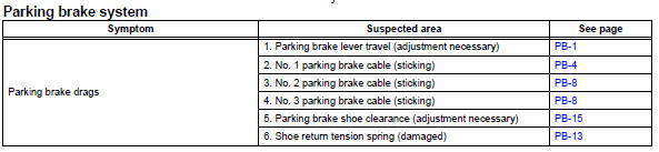
Problem symptoms table
Hint:
Use the table below to help determine the cause of the problem symptom. The potential causes of the symptoms are listed in order of probability in the "suspected area" column of the table. Check each symptom by checking the suspected areas in the order they are listed. Replace parts as necessary.
Adjustment
- Check parking brake lever travel
- Pull the lever upward with a force of approximately 200 n (20 kgf, 44 lbf) and count the number of clicks.
Ok: 7 to 9 clicks (without rear brake dragging)
- Remove upper rear console panel subassembly (see page ip-19)
- Loosen lock nut and no. 1 Wire adjusting nut
- Remove rear wheel
- Adjust parking brake shoe clearance (see page pb-17)
- Install rear wheel torque: 103 n*m (1,050 kgf*cm, 76 ft.*Lbf)
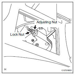
- Adjust parking brake lever travel
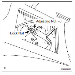
- Turn the no. 1 Wire adjusting nut until the lever travel is correct.
Ok: 7 to 9 clicks (without rear brake dragging) <lever pulling force: approximately 200 n (20 kgf, 44 lbf)>
- Tighten the lock nut.
Torque: 6.0 N*m (61 kgf*cm, 53 in.*Lbf)
- Operate the parking brake lever 3 to 4 times, and check the parking brake lever travel.
Ok: 7 to 9 clicks (without rear brake dragging) <lever pulling force: approximately 200 n (20 kgf, 44 lbf)>
- When operating the parking brake lever, check that the brake warning light illuminates at the first click.
Standard condition: brake warning light always illuminates at the first click.
 Rear brake flexible hose
Installation
Hint:
Use the same procedures for the lh side and rh side.
The procedures listed below are for the lh side.
Install rear brake tube flexible hose
Notice:
The gasket and u ...
 Brake control
...
Other materials:
Open in pump motor circuit
Description
The motor relay drives the pump motor based on a signal from the skid control
ecu.
Wiring diagram
Refer to dtc c0273/13, c0274/14, c1361/91 (see page bc-79).
Inspection procedure
Perform active test by intelligent tester (motor relay)
Select the active test, gener ...
Electronic control
Removal and installation of battery
terminal
Notice:
Certain systems need to be initialized after
disconnecting and reconnecting the cable from
the negative (-) battery terminal.
Before performing electronic work, disconnect
the cable from the negative (-) battery terminal to
...
Bluetooth®
When using the bluetooth® audio system
In the following conditions, the system may not function.
If the portable audio player is turned off
If the portable audio player is not connected
If the portable audio player’s battery is low
There may be a delay if a cellular phone connection i ...
