
Toyota RAV4 (XA40) 2013-2018 Service Manual: Rear brake flexible hose
Installation
Hint:
- Use the same procedures for the lh side and rh side.
- The procedures listed below are for the lh side.
- Install rear brake tube flexible hose
Notice:
The gasket and union bolt must be used as a set, as shown in the illustration.
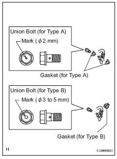
- Connect the flexible hose with new gasket(s) and the union bolt to the disc brake cylinder.
Torque: 30.4 N*m (310 kgf*cm, 22 ft.*Lbf)
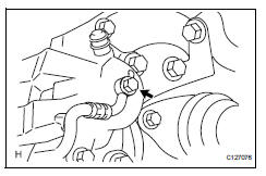
Hint:
Install the flexible hose lock securely in the lock hole in the cylinder.
- Set the flexible hose to the connecting point with the brake tube (labeled a), and then attach a new clip (labeled b).
- Using sst, connect the flexible hose to the brake tube (labeled a) while holding the flexible hose with a wrench.
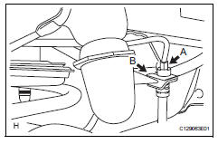
Sst 09023-00101
Torque: 15.2 N*m (155 kgf*cm, 11 ft.*Lbf) without sst
14 N*m (144 kgf*cm, 10 ft.*Lbf) with sst
Hint:
Use a torque wrench with a fulcrum length of 30 cm (11.81 In.).
Notice:
- Do not bend or damage the brake tube.
- Do not allow any foreign matter such as dirt and dust to enter the brake tube from the connecting point.
- Fill reservoir with brake fluid (see page br- 6)
- Bleed air from brake master cylinder (see page br-7)
- Bleed air from brake line (see page br-7)
- Bleed air from abs and traction actuator assembly (see page br-8)
- Check brake fluid level in reservoir (see page br-6)
- Check for brake fluid leakage
- Install rear wheel torque: 103 n*m (1,050 kgf*cm, 76 ft.*Lbf)
 Brake rear brake flexible hose
Components
Removal
Hint:
Use the same procedures for the lh side and rh side.
The procedures listed below are for the lh side.
Remove rear wheel
Drain brake fluid
Notice:
Wash ...
 Parking brake system
Problem symptoms table
Hint:
Use the table below to help determine the cause of the
problem symptom. The potential causes of the symptoms are
listed in order of probability in the "suspected ...
Other materials:
Road test
Inspect set switch
Push the main switch on.
Drive at a desired speed (40 km/h (25 mph) or
higher).
Inspect "+" switch
Push the main switch button on.
Drive at a desired speed (40 km/h (25 mph) or
higher).
Press the control switch to -/set. ...
Wheels
If a wheel is bent, cracked or
heavily corroded, it should
be replaced. Otherwise, the
tire may separate from the
wheel or cause a loss of
handling control.
Wheel selection
When replacing wheels, care
should be taken to ensure that
they are equivalent to those
removed in load capacity, diameter,
rim ...
Diagnosis system
Bus check
Select "bus check" from the "obd / mobd
menu" screen.
Hint:
The ecus and sensors that are properly connected
to the can communication system can be displayed
using the intelligent tester via can vim.
Press "enter" on the intelligen ...
