Toyota RAV4 (XA40) 2013-2018 Service Manual: Fuel tank
Components
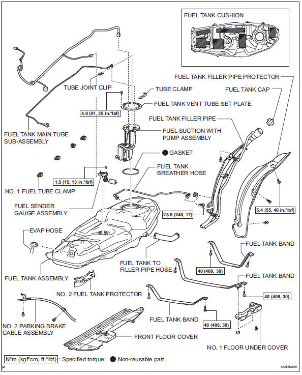
Removal
- Discharge fuel system pressure (see page fu-9)
- Disconnect cable from negative battery terminal
Caution:
Wait at least 90 seconds after disconnecting the cable from the negative (-) battery terminal to prevent airbag and seat belt pretensioner activation.
- Remove fuel tank cap
- Remove front floor cover
- Remove the nut, bolt, 3 clips and floor cover.
- Remove no. 1 Floor under cover
- Remove the 2 nuts, clip and floor under cover.
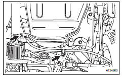
- Disconnect no. 2 Parking brake cable assembly
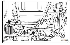
- Remove the 2 bolts and disconnect the parking brake cable.
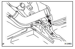
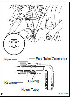
- Disconnect fuel tank main tube subassembly
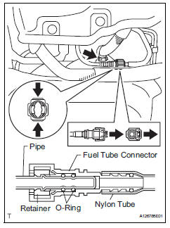
- Pinch and pull the main tube connector to disconnect the connector from the pipe.
Notice:
- Check for foreign matter in the pipe and
around the connector. Clean if necessary.
Foreign matter may damage the o-ring or cause leaks in the seal between the pipe and connector.
- Do not use any tools to separate the pipe and connector.
- Do not forcefully bend or twist the nylon tube.
- Check for foreign matter on the pipe seal surface. Clean if necessary.
- Put the pipe and connector ends in plastic bags to prevent damage and foreign matter contamination.
- If the pipe and connector are stuck together, pinch the connector between your fingers and turn it carefully to disconnect it.
- Disconnect the evap hose from the tank.
- Disconnect fuel tank to filler pipe hose

- Disconnect the filler pipe hose from the fuel tank.
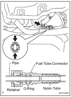
- Disconnect fuel tank breather hose
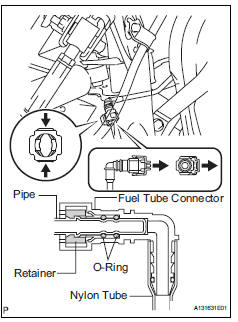
- Disconnect the breather hose from the fuel tank.
Notice:
- Check for foreign matter in the pipe and
around the connector. Clean if necessary.
Foreign matter may damage the o-ring or cause leaks in the seal between the pipe and connector.
- Do not use any tools to separate the pipe and connector.
- Do not forcefully bend or twist the nylon tube.
- Check for foreign matter on the pipe seal surface. Clean if necessary.
- Put the pipe and connector ends in plastic bags to prevent damage and foreign matter contamination.
- If the pipe and connector are stuck together, pinch the connector between your fingers and turn it carefully to disconnect it.
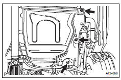
- Remove fuel tank filler pipe
- Remove the 3 bolts and filler pipe protector.
- Remove the 2 bolts and filler pipe.
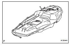
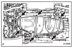
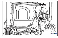
- Remove fuel tank assembly
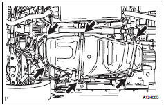
- Set a mission jack underneath the fuel tank.
- Remove the 6 bolts and 3 fuel tank bands.
- Slightly lower the mission jack.
Notice:
Be careful not to cut the wirings.
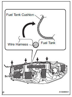
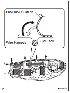
- Fold back approximately half of each cushion rubber so that the wire harness can be detached from the fuel tank in the step below.
- Disconnect the fuel pump connector and sender gauge connector.
Notice:
- Before this procedure, check the connector for dirt, mud or other contamination.
- Do not use any tools in this procedure.
- Detach the wire harness from the 4 clamps and remove the fuel tank.
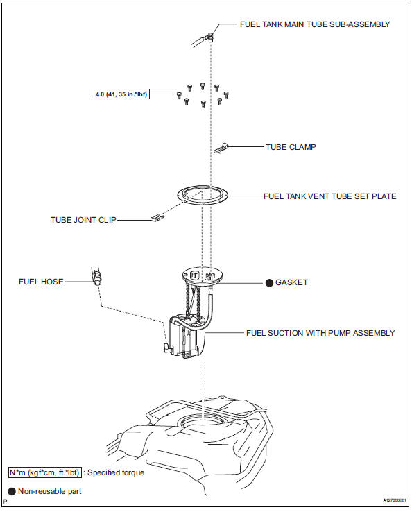
Disassembly
- Remove fuel tank main tube sub-assembly (see page fu-30)
- Remove fuel tank vent tube set plate (see page fu-30)
- Remove fuel suction with pump assembly (see page fu-30)
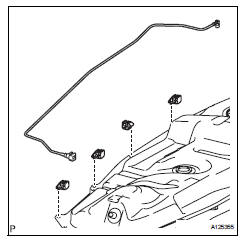
- Remove fuel tank main tube sub-assembly
- Remove the tube from the fuel tube clamps.
- Remove no. 1 Fuel tube clamp
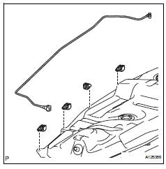
- Remove the 4 tube clamps from the fuel tank.
- Remove no. 1 Fuel tank cushion
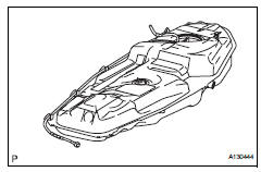
- Remove the 7 fuel tank cushions from the fuel tank.
- Remove fuel sender gauge assembly
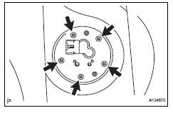
- Remove the 5 screws and sender gauge.
Reassembly
- Install fuel sender gauge assembly
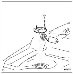
- Install the sender gauge with the 5 bolts.
Torque: 1.5 N*m (15 kgf*cm, 13 in.*Lbf)
- Install no. 1 Fuel tank cushion
- Install 7 new fuel tank cushions onto the fuel tank as shown in the illustration.
- Install no. 1 Fuel tube clamp
- Install the 4 tube clamps to the fuel tank.
- Install fuel tank main tube sub-assembly
- Install the tube with the 4 clips.
- Install fuel suction with pump assembly (see page fu-36)
- Install fuel tank vent tube set plate (see page fu-36)
- Install fuel tank main tube sub-assembly (see page fu-37)
Installation
- Install fuel tank assembly
- Set the fuel tank on a mission jack.
- Lift up the mission jack.
- Fold back the 2 cushion rubbers.
- Connect the fuel pump connector and sender gauge connector to the fuel tank.
Notice:
Be careful not to cut the wirings.
- Attach the wire harness to the 4 clamps.
- Install the 3 fuel tank bands with the 6 bolts.
Torque: 40 n*m (408 kgf*cm, 30 ft.*Lbf)
- Install fuel tank filler pipe
- Install the filler pipe with the 2 bolts.
Torque: 23.5 N*m (240 kgf*cm, 17 ft.*Lbf)
- Install the filler pipe protector with the 3 bolts.
- Connect fuel tank to filler pipe hose
- Connect the filler pipe hose to the fuel tank.
- Connect fuel tank breather hose
- Connect the fuel tank breather hose to the fuel tank.
Notice:
- Before installing the tube connector to the pipe, check the connector for damage and foreign matter.
- Check that the connector and pipe is securely connected by trying to pull them apart.
- Connect fuel tank main tube sub-assembly
Notice:
Before installing the tube connector to the pipe, check the connector for damage and foreign matter.
- Connect the main tube connector to the pipe. Push the 2 parts together firmly until a "click" sound is heard.
Notice:
Check that the connector and pipe are securely connected by trying to pull them apart.
- Connect the evap hose to the fuel tank.
- Install no. 1 Floor under cover
- Install the floor cover with the clip and 2 nuts.
- Install front floor cover
- Install the floor under cover with the 3 clips, bolt and nut.
- Install no. 2 Parking brake cable assembly
- Install the parking brake cable with the 2 bolts.
- Install fuel tank cap
- Connect cable to negative battery terminal
- Check for fuel leaks (see page fu-14)
 Fuel pump
Components
Removal
Remove fuel tank assembly
Remove the fuel tank (see page fu-39).
Remove fuel tank main tube sub-assembly
Remove the joint clip and fuel tank main tube ...

Other materials:
Auto lsd indicator light remains on
Description
This is the auto lsd switch for 2wd. When the auto lsd switch is pushed on,
the auto lsd function is
available and the auto lsd indicator light illuminates.
Hint:
The auto lsd does not operate even if the auto lsd switch is pressed under
the following conditions:
The trc or v ...
Driving mode select switch
The driving modes can be
selected to suit the driving
and usage conditions.
Selecting a driving mode
‚ñÝ FF vehicles/Dynamic
Torque Control AWD vehicles
Eco drive mode
Suitable for driving to improve fuel
economy by more smoothly generating
torque in response to accelerator
pedal operations comp ...
Clock
The clock can be adjusted by pressing the buttons.
Adjusts the hours.
Adjusts the minutes.
The clock is displayed when
Vehicles without a smart key system
The engine switch is in the “acc” or “on” position.
Vehicles with a smart key system
The engine switch is in a ...
