Toyota RAV4 (XA40) 2013-2018 Service Manual: Fuel pump
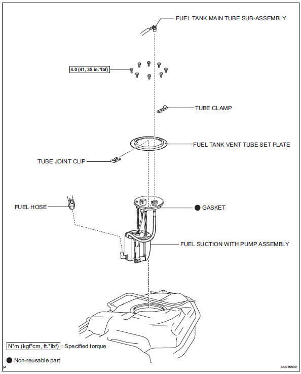
Components
Removal
- Remove fuel tank assembly
- Remove the fuel tank (see page fu-39).
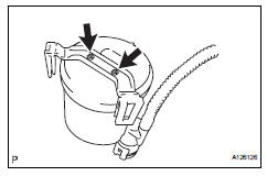
- Remove fuel tank main tube sub-assembly
- Remove the joint clip and fuel tank main tube.
Caution:
- Before removing the tube joint clip, check for foreign matter around the clip. Clean if necessary.
- Keep the o-ring free of foreign matter, as it becomes contaminated easily.
- Do not use any tools in this procedure.
- Do not forcefully bend or twist the tube.
- Put the tube in a plastic bag to prevent damage and contamination.
- If the fuel suction plate and tube are stuck together, pinch the tube and turn it carefully to disconnect it.
- Be careful not to damage the clip. If the clip is damaged, replace it.
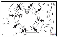
- Remove fuel tank vent tube set plate
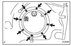
- Remove the 8 bolts and set plate.
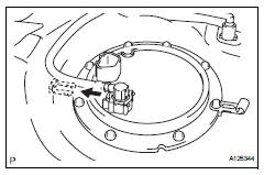
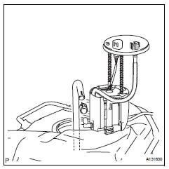
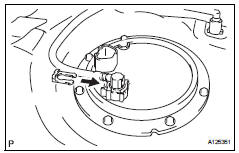
- Remove fuel suction with pump assembly
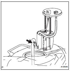
- Disconnect the fuel hose and remove the fuel pump from the fuel tank.
Notice:
Do not damage the fuel pump.
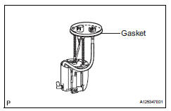
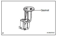
- Remove the gasket from the fuel pump.
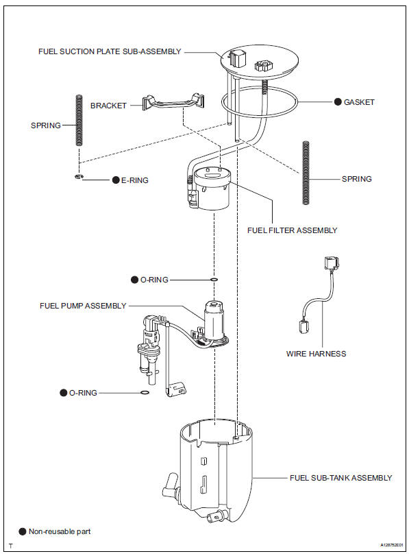
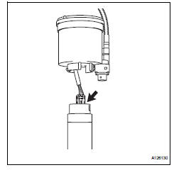
- Remove fuel sub-tank assembly
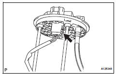
- disconnect the wire harness.
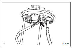
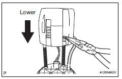
- Using needle nose pliers, remove the e-ring.
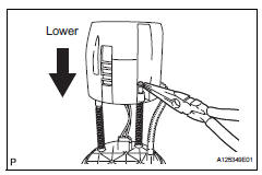
Hint:
Slightly lower the sub-tank to remove the e-ring.
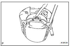
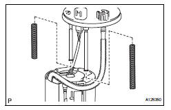
- Remove the 2 springs from the 2 shaft.
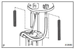
- Remove the 2 springs from the 2 shaft.
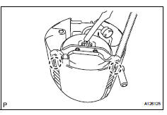
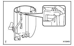
- Detach the 2 claws and remove the sub-tank.
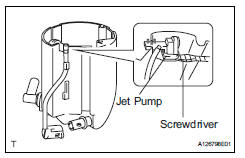
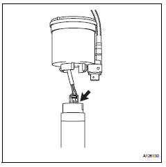
- Disengage the claw of the jet pump nozzle.
- Using a screwdriver with the tip taped, remove the jet pump.
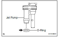
- Remove the o-ring from the jet pump.
- Remove bracket
- Using a screwdriver, detach the 2 claws and remove the bracket.
Hint:
Tape the screwdriver tip before use.
- Remove fuel pump assembly
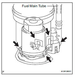
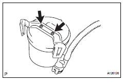
- Detach the 5 claws on the filter and remove the fuel pump from the fuel filter.
Hint:
When removing the claw, do not disconnect the fuel main tube.
- Disconnect the fuel pump connector.
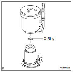
- Remove the o-ring from the fuel filter.
Inspection
- Inspect fuel pump
- Check the fuel pump resistance.
- Measure the resistance between terminals 1 and 2.
Standard resistance: 0.2 To 3.0 ٠at 20°c (68°f)
If the result is not as specified, replace the fuel pump.
- Check fuel pump operation.
- Apply battery voltage to terminals 1 and 2.
Check that the pump operates.
Notice:
- These tests must be completed within 10 seconds to prevent the coil from burning out.
- Keep the fuel pump as far away from the battery as possible.
- Always the voltage on and off on the battery side, not the fuel pump side.
If the pump does not operate, replace the fuel pump.
Installation
- Install fuel pump assembly
- Connect the pump harness connector.
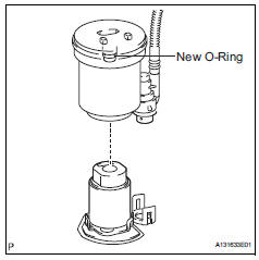
- Apply gasoline to a new o-ring and install the o-ring to the fuel filter.
- Attach the 5 claws to the claw holes and install the fuel pump.
- Install bracket
- Attach the 2 claws to the claw holes and install the bracket.
- Install fuel sub-tank assembly
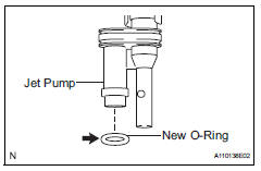
- Apply gasoline to a new o-ring and install it to the jet pump.
- Install the jet pump while aligning it to the installation position of the sub-tank.
- Install the jet pump nozzle.
- Attach the 2 claws to the claw holes and install the fuel sub-tank.
- Connect the wire harness.
- Install the spring to the fuel suction plate shaft and install them to the sub-tank.
- Using needle-nose pliers, install a new e-ring.
Hint:
Slightly lower the sub-tank to install the e-ring.
- Install fuel suction with pump assembly
- Install a new gasket onto the fuel pump.
Connect the fuel hose and install the fuel pump into the fuel tank.
Notice:
Do not damage the fuel pump filter.
- Install fuel tank vent tube set plate
- Install the set plate with the 8 bolts.
Torque: 4.0 N*m (41 kgf*cm, 35 in.*Lbf)
- Install fuel tank main tube sub-assembly
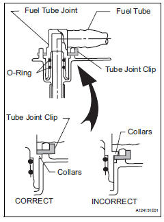
- Install the fuel tube with the joint clips.
Caution:
- Check that there are no scratches or foreign objects on the connecting parts.
- Check that the fuel tube joint is inserted securely.
- Check that the fuel tube joint clip is on the collars of the fuel tube joint.
- After installing the tube joint clip, check that the fuel tube joint has not been pulled off.
- Be careful not to damage the clip. If the clip is damaged, replace it.
Install fuel tank assembly
- Install the fuel tank (see page fu-44).
 Fuel pressure pulsation damper
Components
Removal
Discharge fuel system pressure (see page
fu-9)
Disconnect cable from negative battery
terminal
Remove no. 1 Engine cover (see page es-410)
Remove air cleaner ...
 Fuel tank
Components
Removal
Discharge fuel system pressure (see page
fu-9)
Disconnect cable from negative battery
terminal
Caution:
Wait at least 90 seconds after disconnecting the
cabl ...
Other materials:
Installation
Install crankshaft position sensor
Notice:
Make sure that the o-ring is not cracked or jammed
when installing it.
Apply a light coat of engine oil to the o-ring of the
sensor.
Install the sensor with the bolt.
Torque: 9.0 N*m (90 kgf*cm, 80 in.*Lbf)
Install the wire ha ...
Bus ic communication malfunction
Description
The air conditioning harness connects the air conditioning amplifier and the
servos. The air conditioning
amplifier supplies power and sends operation instructions to each servo through
the air conditioning
harness. Each servo sends damper position information to the air condi ...
Intuitive parking assist
The distance from your
vehicle to objects, such as a
wall, when parallel parking
or maneuvering into a
garage is measured by the
sensors and communicated
via the multi-information
display or Multimedia Display
and a buzzer. Always
check the surrounding area
when using this system.
System components
...
