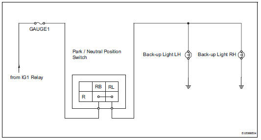
Toyota RAV4 (XA40) 2013-2018 Service Manual: Back-up light circuit
Description
The park / neutral position switch turns on when the shift lever is moved into the r position, causing the back-up lights to illuminate.
Wiring diagram
Inspection procedure
- Inspect fuse (gauge1)
- Remove the gauge1 fuse from the instrument panel junction block.
- Measure the resistance of the fuse.
Standard resistance:
below 1

- Inspect back-up light
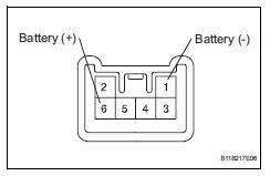
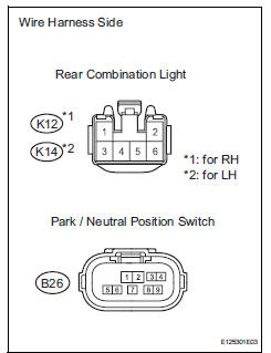
- Remove the rear combination light.
- Connect the positive (+) lead from the battery to terminal 6 and the negative (-) lead to terminal 1, then check that the light comes on.
Ok: light comes on.

- Inspect park / neutral position switch
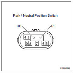
- Disconnect the b26 park / neutral position switch connector.
- Measure the resistance of the switch.
Standard resistance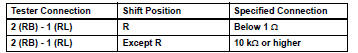

- check wire harness (park / neutral position switch - battery)
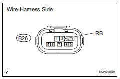
- Disconnect the b26 park / neutral position switch connector.
- Measure the voltage of the wire harness side connector.
Standard voltage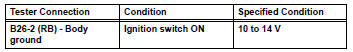

- Check wire harness (park / neutral position switch - back-up light)
- Disconnect the b26 park / neutral position switch connector.
- Disconnect the k12 and k14 rear combination light assembly connectors
- Measure the resistance of the wire harness side connectors.
Standard resistance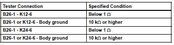

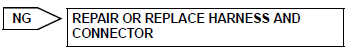
Repair or replace harness and connector (back-up light - body ground)
 Hazard warning switch circuit
Description
When the hazard warning signal switch is turned on, the turn signal flasher
relay (marking: flsh) in the
main body ecu turns on to flash the hazard warning signal lights.
Wiring diagr ...
 Light control switch circuit
Description
This circuit detects the state of the headlight dimmer switch.
Wiring diagram
Inspection procedure
Read value of intelligent tester (main body ecu)
Connect the intelligent ...
Other materials:
Terminals of ecm
Check ecm
Disconnect the a9 and b30 connectors.
Measure the voltage and resistance of the wire
harness side connectors.
If the result is not as specified, there may be a
malfunction on the wire harness side. ...
Inspection
Inspect starter assembly
Notice:
These tests must be performed within 3 to 5 seconds
to avoid burning out the coil.
Perform the pull-in test.
Disconnect the lead wire from terminal c.
Connect the battery to the magnetic switch as
shown in the illustration. Check that the clutch ...
How to proceed with troubleshooting
Hint:
Use these procedures to troubleshoot the supplemental
restraint system.
*: Use the intelligent tester.
Vehicle brought to workshop
Inspect battery voltage*
Standard voltage:
11 to 14 v
If the voltage is below 11 v, recharge or replace the battery
before proceeding.
...
