Toyota RAV4 (XA40) 2013-2018 Service Manual: Data list / active test
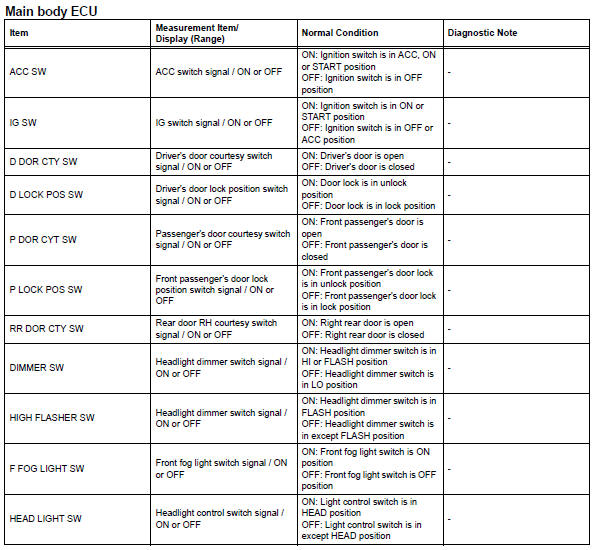
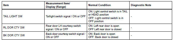
- Read data list
Hint:
Using the intelligent tester's data list allows switch, sensor, actuator and other item values to be read without removing any parts. Reading the data list early in troubleshooting is one way to save time.
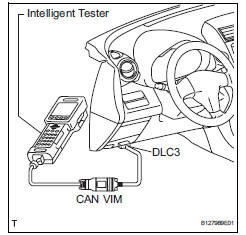
- Connect the intelligent tester (with can vim) to the dlc3.
- Turn the ignition switch on.
- Read the data list according to the display on the tester.
- Perform active test
Hint:
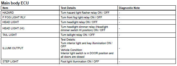
Performing the intelligent tester's active test allows relay, vsv, actuator and other items to be operated without removing any parts. Performing the active test early in troubleshooting is one way to save time.
The data list can be displayed during the active test.
- Connect the intelligent tester (with can vim) to the dlc3.
- Turn the ignition switch on.
- Perform the active test by following the directions on the tester screen.
- Stop light switch circuit
- Headlight relay circuit
- Drl relay circuit
- Headlight (hi-beam) circuit
- Front fog light circuit
- Turn signal light circuit
- Hazard warning switch circuit
- Back-up light circuit
- Light control switch circuit
- Door courtesy switch circuit
- Door lock position circuit
- Footwell light circuit
- Illumination circuit
- Taillight relay circuit
 Terminals of ecu
Check instrument panel junction block (main body ecu)
Measure the voltage of the connectors.
If the result is not as specified, the junction block
(main body ecu) may have ...
 Stop light switch circuit
Description
When the stop light switch is turned on, current flows to the stop lights to
illuminate them.
Wiring diagram
Inspection procedure
Inspect fuse (stop)
Remove the stop fus ...
Other materials:
Diagnostic trouble code chart (2006/01- )
Hint:
When the air conditioning system functions properly, dtc
b1400/00 is output.
Hint:
*1: Dtc b1422/22 (compressor lock sensor circuit) is
indicated only for a currently occurring malfunction for 2grfe.
*2: Compressor and pulley for 2az-fe, compressor and
magnetic clutch for 2gr-fe ...
How to proceed with troubleshooting (2005/11-2006/01)
Hint:
Use these procedures to troubleshoot the air conditioning
system.
*: Use the intelligent tester.
Vehicle brought to workshop
Customer problem analysis and symptom check
Inspect battery voltage
Standard voltage:
11 to 14 v
If the voltage is below 11 v, rechar ...
Back-up light circuit
Description
The park / neutral position switch turns on when the shift lever is moved
into the r position, causing the
back-up lights to illuminate.
Wiring diagram
Inspection procedure
Inspect fuse (gauge1)
Remove the gauge1 fuse from the instrument panel
junction block.
Meas ...
