Toyota RAV4 (XA40) 2013-2018 Service Manual: Headlight relay circuit
Description
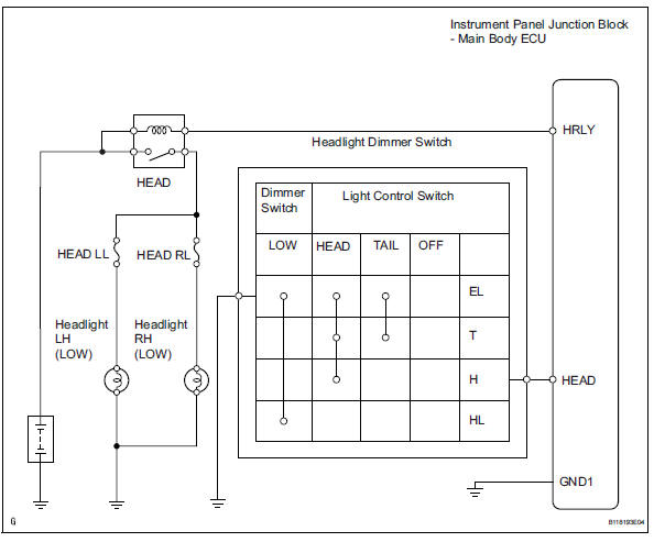
When the light control switch, located on the headlight dimmer switch, is turned to the head position, the head relay illuminates the headlights.
Wiring diagram
Inspection procedure
- Perform active test by intelligent tester (headlight)
- Connect the intelligent tester (with can vim) to the dlc3.
- Turn the ignition switch on and press the intelligent tester main switch on.
- Select the item below in the active test and then check the relay operation.

Ok: headlight comes on

- Inspect fuse (head ll, head rl)
- Remove the head ll fuse and head rl fuse from the engine room no. 2 Relay block.
- Measure the resistance of the fuses.
Standard resistance:
below 1 

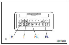
- Inspect headlight relay (marking: head)
- Remove the headlight relay from the engine room no. 2 Relay block.
- Measure the resistance of the relay.
Standard resistance 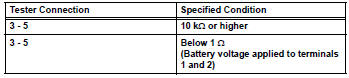

- Inspect bulb (headlight bulb)
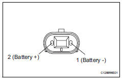
- Remove the headlight bulbs (low).
- Connect the positive (+) lead from the battery to terminal 2 and the negative (-) lead to terminal 1, then check that the bulb illuminates.
Ok: bulb illuminates.

- Check wire harness (main body ecu - battery)
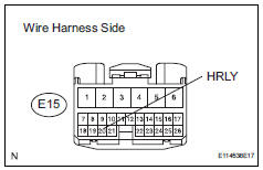
- Disconnect the e15 main body ecu connector.
- Measure the voltage of the wire harness side connector.
Standard voltage 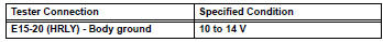

- Check instrument panel junction block (main body ecu)
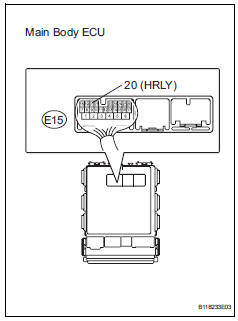
- Measure the voltage of the main body ecu.
Standard voltage 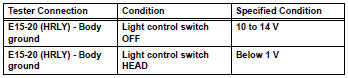

Repair or replace harness and connector (head relay - headlight bulb and body ground)
- Check wire harness (headlight dimmer switch - main body ecu)
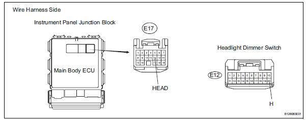
- Disconnect the e17 main body ecu connector.
- Disconnect the e12 headlight dimmer switch connector.
- Measure the resistance of the wire harness side connectors.
Standard resistance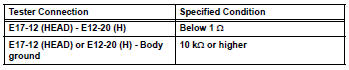

- Inspect headlight dimmer switch
- Disconnect the e12 headlight dimmer switch.
- Measure the resistance of the switch.
Standard resistance 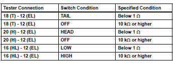

Repair or replace harness and connector (headlight dimmer switch - body ground)
 Stop light switch circuit
Description
When the stop light switch is turned on, current flows to the stop lights to
illuminate them.
Wiring diagram
Inspection procedure
Inspect fuse (stop)
Remove the stop fus ...
 Drl relay circuit
Description
The main body ecu controls the daytime running light no. 2 Relay (marking:
drl no.2).
Wiring diagram
Inspection procedure
Inspect daytime running light relay (marking: drl no. ...
Other materials:
Wireless remote
control/electronic
key battery
Replace the battery with a new one if it is depleted.
You will need the following items:
Flathead screwdriver
Small flathead screwdriver
Lithium battery cr2016 (vehicles without a smart key system), or
cr2032 (vehicles with a smart key system)
Replacing the battery
Vehicles without a ...
Center power outlet socket
Components
Removal
Disconnect cable from negative battery
terminal
Caution:
Wait at least 90 seconds after disconnecting the
cable from the negative (-) battery terminal to
prevent airbag and seat belt pretensioner activation.
Remove no. 1 Console upper panel garnish
(see page ...
Windshield wipers
and washer
Operating the wiper lever
The wiper operation is selected by moving the lever as follows.
For the u.S.A.
Intermittent operation
Low speed operation
High speed operation
Temporary operation
If equipped, wiper intervals can be adjusted when intermittent operation
is select ...
