Toyota RAV4 (XA40) 2013-2018 Service Manual: Drl relay circuit
Description
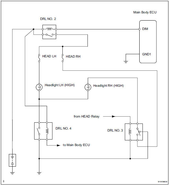
The main body ecu controls the daytime running light no. 2 Relay (marking: drl no.2).
Wiring diagram
Inspection procedure
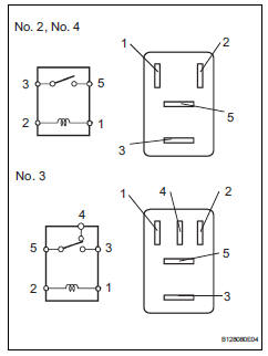
- Inspect daytime running light relay (marking: drl no. 2, Drl no. 3, Drl no. 4)
- Remove the no. 2 Relay, no. 3 Relay and no. 4 Relay from the engine room no. 2 Relay block.
- Measure the resistance of the relays.
Standard resistance:
No. 2, No. 4 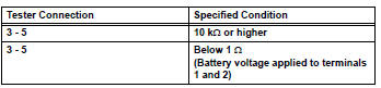
No. 3 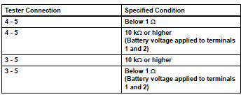

- Inspect fuse (head lh)
- Remove the head lh fuse from the engine room no. 2 Relay block.
- Measure the resistance of the fuse.
Standard resistance:
below 1 

- Inspect headlight bulb (high)
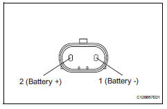
- Remove the headlight bulb (high).
- Connect the positive (+) lead from the battery to terminal 2 and the negative (-) lead to terminal 1, then check that the bulb illuminates.

- Check wire harness (battery - no. 2 Daytime running light relay)
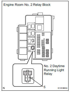
- Remove the no. 2 Daytime running light relay from the engine room no. 2 Relay block.
- Measure the voltage of the relay block.
Standard voltage 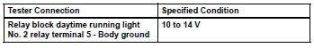

- Check wire harness (no. 2 Daytime running light relay - headlight bulb and body ground)
- Remove the no. 2 Daytime running light relay from the engine room no. 2 Relay block.
- Disconnect the a14 and a22 headlight (high) connectors.
- Measure the resistance of the wire harness side connectors and relay block.
Standard resistance 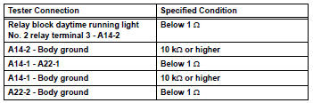

- Check wire harness (main body ecu - battery)
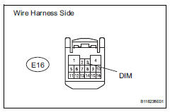
- Disconnect the e16 main body ecu connector.
- Measure the voltage of the wire harness side connector.
Standard voltage 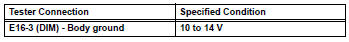

Replace instrument panel junction block (main body ecu)
 Headlight relay circuit
Description
When the light control switch, located on the headlight dimmer switch, is
turned to the head position, the
head relay illuminates the headlights.
Wiring diagram
Inspection proced ...
 Headlight (hi-beam) circuit
Description
The body ecu controls the headlight relay, no. 2 Daytime running light relay
(marking: drl no. 2) And
no. 4 Daytime running light relay (marking: drl no. 4).
Wiring diagram
I ...
Other materials:
Battery temperature sensor circuit
Description
The battery temperature sensor installed on the battery current sensor
detects battery temperature.
A thermistor is integrated into the battery temperature sensor, and the
resistance in the battery
temperature sensor changes according to the battery temperature.
The r ...
Wireless remote
control/electronic
key battery
Replace the battery with a new one if it is depleted.
You will need the following items:
Flathead screwdriver
Small flathead screwdriver
Lithium battery cr2016 (vehicles without a smart key system), or
cr2032 (vehicles with a smart key system)
Replacing the battery
Vehicles without a ...
Handling of hose clamps
Before removing the hose, check the clamp position
so that it can be reinstalled in the same position.
Replace any deformed or dented clamps with new
ones.
When reusing a hose, attach the clamp on the
clamp track portion of the hose.
For a spring type clamp, you may want to spread ...
