Toyota RAV4 (XA40) 2013-2018 Service Manual: Door courtesy switch circuit
Description
The main body ecu detects the condition of the door courtesy switch.
Wiring diagram
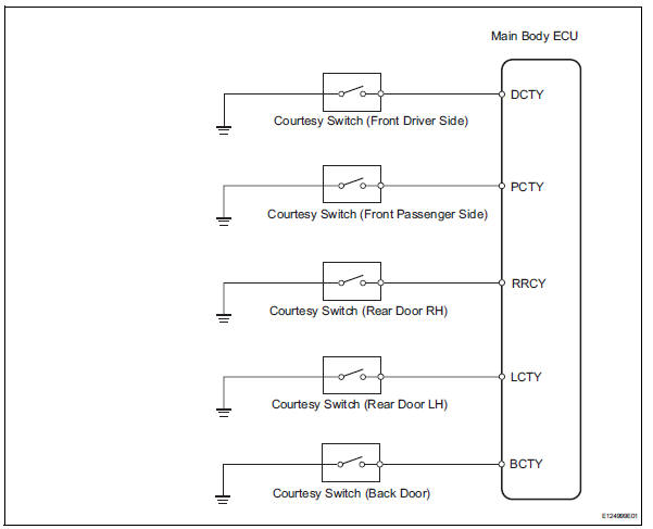
Inspection procedure
- Read value of intelligent tester (door courtesy light switch)
- Connect the intelligent tester (with can vim) to the dlc3.
- Turn the ignition switch to the on position and press the intelligent tester main switch on.
- Select the items below in the data list, and read the displays on the intelligent tester.
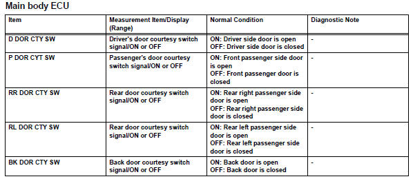
Ok: condition sign can be displayed.

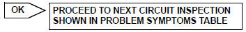
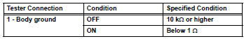
- Inspect courtesy light switch
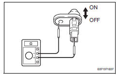
- Remove the door courtesy light switch.
- Measure the resistance of the switch.
Standard resistance:
front lh, front rh, rear lh, rear rh, back door

- Check wire harness (main body ecu - courtesy light switch)
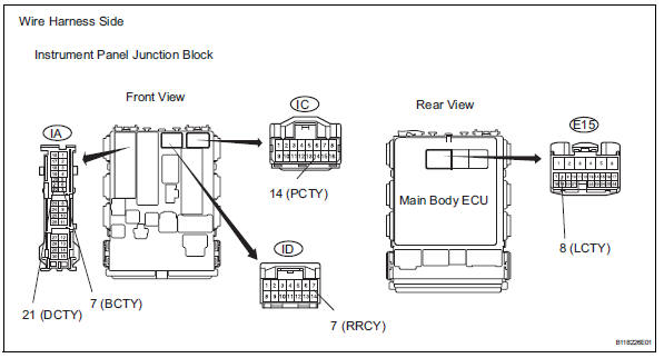
- Connect the courtesy light switch.
- Disconnect the ia, ic and id instrument panel junction block connectors.
- Disconnect the e15 main body ecu connector.
- Measure the resistance of the wire harness side connectors.
Standard resistance:
Front door lh 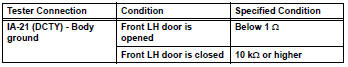
Front door rh 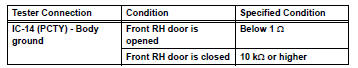
Rear door rh 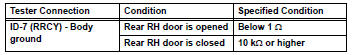
Rear door lh 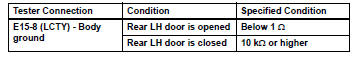
Back door 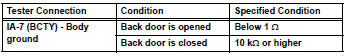

Replace instrument panel junction block (main body ecu)
 Light control switch circuit
Description
This circuit detects the state of the headlight dimmer switch.
Wiring diagram
Inspection procedure
Read value of intelligent tester (main body ecu)
Connect the intelligent ...
 Door lock position circuit
Description
This circuit detects the state of the door lock detection sensor and sends it
to the main body ecu.
Wiring diagram
Inspection procedure
Read value of intelligent tester (door ...
Other materials:
Window lock switch
Press the switch to lock the passenger
window switches.
Use this switch to prevent children
from accidentally opening or closing
a passenger window.
The power windows can be operated when
Vehicles without a smart key system
The engine switch is in the “on” position.
Vehicles ...
Operation flow
Hint:
Perform troubleshooting in accordance with the
procedures below. The following is an outline of basic
troubleshooting procedures. Confirm the troubleshooting
procedures for the circuit you are working on before
beginning troubleshooting.
Ask
the customer about the conditions and en ...
Using the cd player
Power
Volume
Cd eject
Selecting a track or displaying
track list
Searching playback
Random play or back button
Repeat play
Fast-forwarding or rewinding
Changing the audio source/
playback
Playback/pause
Selecting a track
Displaying text message
Loading cds
Insert ...
