Toyota RAV4 (XA40) 2013-2018 Service Manual: Door lock position circuit
Description
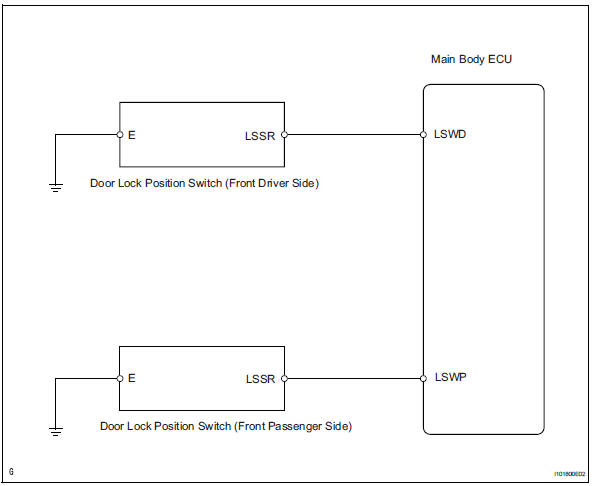
This circuit detects the state of the door lock detection sensor and sends it to the main body ecu.
Wiring diagram
Inspection procedure
- Read value of intelligent tester (door lock position)
- Connect the intelligent tester (with can vim) to the dlc3.
- Turn the ignition switch to the on position and press the intelligent tester main switch on.
- Select the items below in the data list, and read the displays on the intelligent tester.
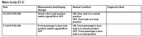
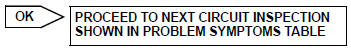
Ok: condition sign can be displayed.

- Inspect front door lock
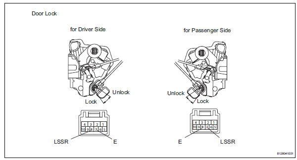
- Remove the front door lock (driver side or passenger side).
- Measure the resistance of the door lock.
Standard resistance:
front door lock (for driver side) 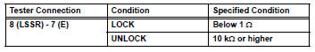
Front door lock (for passenger side)
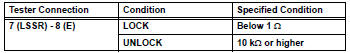

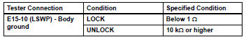
- Check wire harness (main body ecu - door lock and body ground)
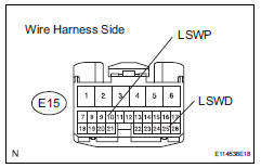
- Disconnect the e15 main body ecu connector.
- Measure the resistance of the wire harness side connector.
Standard resistance:
front door lock (for driver side) 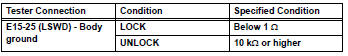
Front door lock (for passenger side)

Replace instrument panel junction block (main body ecu)
 Door courtesy switch circuit
Description
The main body ecu detects the condition of the door courtesy switch.
Wiring diagram
Inspection procedure
Read value of intelligent tester (door courtesy light switch)
Conn ...
 Footwell light circuit
Description
The main body ecu receives information regarding the door lock position
switch and ignition switch, and
turns on each foot light.
Wiring diagram
Inspection procedure
Perform ...
Other materials:
Catalyst monitor (active air-fuel ratio control type)
Preconditions
The monitor will not run unless:
The mil is off.
Drive pattern
Connect the intelligent tester to the dlc3.
Turn the ignition switch on.
Turn the tester on.
Clear dtcs (if set) (see page es-35).
Start the engine and warm it up.
Drive the vehicle at be ...
Removal
Disconnect cable from negative battery
terminal
Caution:
Wait at least 90 seconds after disconnecting the
cable from the negative (-) battery terminal to
prevent airbag and seat belt pretensioner activation.
Remove rear door scuff plate rh (see page
ir-29)
Remove package tray trim ...
Transmitter id
Description
Hint:
It is necessary to perform the procedure to identify the tire pressure
monitor valve that is malfunctioning
because it cannot be identified by the output dtc.
Inspection procedure
Notice:
It is necessary to register an id code after replacing the tire pressure
wa ...
