
Toyota RAV4 (XA40) 2013-2018 Service Manual: Footwell light circuit
Description
The main body ecu receives information regarding the door lock position switch and ignition switch, and turns on each foot light.
Wiring diagram
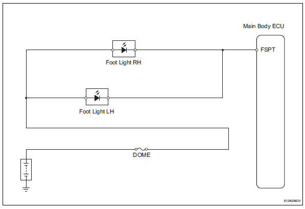
Inspection procedure
- Perform active test by intelligent tester (main body ecu)
- Connect the intelligent tester (with can vim) to the dlc3.
- Turn the ignition switch to the on position and press the intelligent tester main switch on
- Select the items below in the active test and then check the relay operation.

Ok: light comes on.


- Inspect fuse (dome)
- Remove the dome fuse from the engine room no. 2 Relay block.
- Measure the resistance of the fuse.
Standard resistance:
below 1 


- Inspect foot light
- Remove the foot light.
- Connect the positive (+) lead from the battery to terminal 2 and the negative (-) lead to terminal 1, then check that the light comes on.
Ok: light comes on.


- Check wire harness (battery - main body ecu)
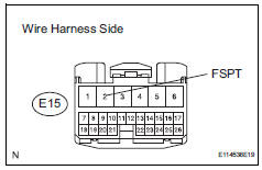
- Install the foot light.
- Disconnect the e15 main body ecu connector.
- Measure the voltage of the wire harness side connector.
Standard voltage 


Replace instrument panel junction block (main body ecu)
 Door lock position circuit
Description
This circuit detects the state of the door lock detection sensor and sends it
to the main body ecu.
Wiring diagram
Inspection procedure
Read value of intelligent tester (door ...
 Illumination circuit
Description
The main body ecu receives information regarding the door courtesy switch and
door lock position
switch, and turns on the room light.
Wiring diagram
Inspection procedure
Perf ...
Other materials:
Blower motor
On-vehicle inspection
Inspect blower motor (for automatic air conditioning system)
Disconnect the blower motor connector.
Connect the positive (+) lead from the battery to
terminal 1 and negative (-) lead to terminal 2, and
then check that the motor operates smoothly.
If the ...
Problem symptoms table (2006/01- )
Hint:
Use the table below to help determine the cause of the
problem symptom. The potential causes of the symptoms
are listed in order of probability in the "suspected area"
column of the table. Check each symptom by checking the
suspected areas in the order they are listed. R ...
System description
General
The air conditioning system has the following
features:
The air conditioning amplifier controls the
operation of parts, such as the a/c compressor,
automatically in accordance with the operating
conditions of the air conditioning system.
Mode position and damper ...
