Toyota RAV4 (XA40) 2013-2018 Service Manual: Brake switch "A" / "B" correlation
![]()
Description
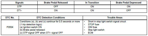
The stop light switch is a duplex system that transmits two signals: stp and st1-. These two signals are used by the ecm to monitor whether or not the brake system is working properly. If the signals, which indicate the brake pedal is being depressed and released, are detected simultaneously, the ecm interprets this as a malfunction in the stop light switch and sets the dtc.
Hint:
The normal conditions are as shown in the table below. The signals can be read using the intelligent tester.
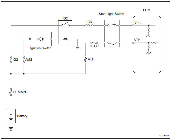
Wiring diagram
Inspection procedure
Hint:
- Read freeze frame data using the intelligent tester. Freeze frame data records the engine condition when malfunctions are detected. When troubleshooting, freeze frame data can help determine if the vehicle was moving or stationary, if the engine was warmed up or not, if the air-fuel ratio was lean or rich, and other data from the time the malfunction occurred.
- Stp signal conditions can be checked using the intelligent tester.
- Connect the intelligent tester to the dlc3.
- Turn the ignition switch on.
- Turn the tester on.
- Select the following menu items: diagnosis / enhanced obd ii / data list / primary / stop light sw.
- Check the stp signal when the brake pedal is depressed and released.

- Check stop light switch assembly (terminal b voltage)
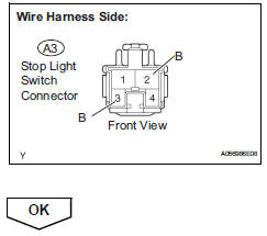
- Disconnect the a3 stop light switch connector.
- Turn the ignition switch on.
- Measure the voltage between the terminals of the a3 stop light switch connector and body ground.
Standard voltage 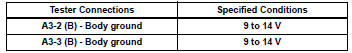
- Reconnect the stop light switch connector.
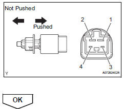
- Inspect stop light switch assembly
- Remove the stop light switch.
- Check the resistance.
Standard resistance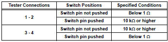
- Reinstall the stop light switch.
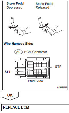
- Check ecm (stp and st1 - voltage)
- Disconnect the a9 ecm connector.
- Turn the ignition switch on.
- Measure the voltage between the terminals st1- and stp of the a9 ecm connector and body ground.
standard voltage 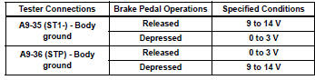
- Reconnect the ecm connector.
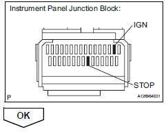
- Inspect fuse (stop and ign fuse)
- Remove the stop and ign fuses from the instrument panel junction block.
- Measure the resistance.
Standard resistance:
below 1 
- Reinstall the stop and ign fuses.
 Vehicle speed sensor "A"
description
The speed sensor detects the wheel speed and sends the appropriate signals to
the skid control ecu.
The skid control ecu converts these wheel speed signals into a 4-pulse signal ...
 Idle control system malfunction
Description
The idling speed is controlled by the etcs (electronic throttle control
system). The etcs is comprised
of: 1) the one valve type throttle body; 2) the throttle actuator, which
op ...
Other materials:
Removal
Discharge refrigerant from
refrigeration system (see page ac-172)
Disconnect cable from negative battery
terminal
Caution:
Wait at least 90 seconds after disconnecting the
cable from the negative (-) battery terminal to
prevent airbag and seat belt pretensioner activation.
Remove ...
Front passenger side seat belt warning light malfunction
Description
When the ignition switch is on, the center airbag sensor transmits front seat
inner belt status signals to
the combination meter through the can bus line. If the front passenger seat belt
is not fastened, the
heater control panel (automatic a/c) or clock (manual a/c) blinks the fr ...
Only driver door lock / unlock functions do not operate
Description
The main body ecu receives lock / unlock switch signals and activates the
door lock motor accordingly.
Wiring diagram
Inspection procedure
Perform active test by intelligent tester (door lock)
Select the active test, use the intelligent tester to
generate a control c ...
