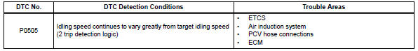
Toyota RAV4 (XA40) 2013-2018 Service Manual: Idle control system malfunction
![]()
Description
The idling speed is controlled by the etcs (electronic throttle control system). The etcs is comprised of: 1) the one valve type throttle body; 2) the throttle actuator, which operates the throttle valve; 3) the throttle position (tp) sensor, which detects the opening angle of the throttle valve; 4) the accelerator pedal position (app) sensor, which detects the accelerator pedal position; and 5) the ecm, which controls the etcs. Based on the target idling speed, the ecm controls the throttle actuator to provide the proper throttle valve opening angle.
Monitor description
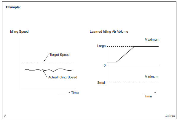
The ecm monitors the idling speed and idling air flow volume to conduct idle speed control (isc). The ecm determines that the isc system is malfunctioning if the following conditions apply:
- The learned idling air flow volume remains at the maximum or minimum volume 5 times or more during a drive cycle.
- After driving at 10 km/h (6.25 Mph) or more, the actual engine idling speed varies from the target idling speed by between 100 rpm and 200 rpm, 5 times or more during a drive cycle.
Example: if the actual idling speed varies from the target idling speed by more than 200 rpm* 5 times during a drive cycle, the ecm illuminates the mil and sets the dtc.
Hint:
*: Threshold idling speed varies with engine load.
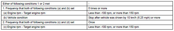
Monitor strategy
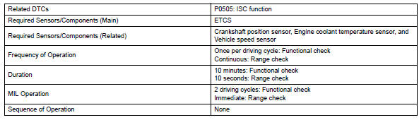
Typical enabling conditions
![]()
Typical malfunction thresholds
![]()
Inspection procedure
Hint:
- The following conditions may also cause dtc p0505 to be set:
- The floor carpet overlapping slightly onto the accelerator pedal, causing the accelerator pedal to be slightly depressed and therefore the throttle valve position to be slightly open.
- The accelerator pedal being not fully released.
- Read freeze frame data using the intelligent tester. Freeze frame data records the engine condition when malfunctions are detected. When troubleshooting, freeze frame data can help determine if the vehicle was moving or stationary, if the engine was warmed up or not, if the air-fuel ratio was lean or rich, and other data from the time the malfunction occurred.
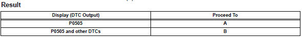
- Check any other dtcs output (in addition to dtc p0505)
- Connect the intelligent tester to the dlc3.
- Turn the ignition switch on.
- Turn the tester on.
- Select the following the menu items: diagnosis / enhanced obd ii / dtc info / current codes.
- Read dtcs.
Hint:
If any dtcs other than p0505 are output, troubleshoot those dtcs first.


- Check pcv hose connections
Ok: pcv hose is connected correctly and is not damaged.


- Check air induction system
- Check the air induction system for vacuum leakage.
Ok:
no leakage from air induction system.


- Check throttle valve
- Check the throttle valve condition.
Ok: throttle valve is not contamainated with foreign objects and moves smoothly.

 Brake switch "A" / "B" correlation
Description
The stop light switch is a duplex system that transmits two signals: stp and
st1-. These two signals are
used by the ecm to monitor whether or not the brake system is working prope ...
 Cold start
Description
The electronic throttle control system (etcs) controls the engine idling
speed. The etcs operates the
throttle actuator to open and close the throttle valve, and adjusts the intake ...
Other materials:
Random / multiple cylinder misfire detected
Description
When the engine misfires, high concentrations of hydrocarbons (hc) enter the
exhaust gas. Extremely
high hc concentration levels can cause increases in exhaust emission levels.
High concentrations of hc
can also cause increases in the three-way catalytic converter (twc) te ...
Air-fuel ratio (a/f) and heated oxygen (ho2) sensor
heater monitors (front a/f and rear ho2 sensor type)
Preconditions
The monitor will not run unless:
The mil is off.
Drive pattern
Connect the intelligent tester to the dlc3.
Turn the ignition switch on.
Turn the tester on.
Clear dtcs (if set) (see page es-35).
Start the engine.
Allow the engine to idle for 10 minute ...
Luggage compartment
features
Cargo hooks
Raise the hooks to use.
The cargo hooks are provided for
securing loose items.
Caution
When the cargo hooks are not in use
To avoid injury, always return the cargo hooks to their stowed
positions.
Grocery bag hooks
Notice
Grocery bag hook weight capacity
Do not hang ...
