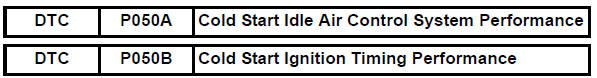
Toyota RAV4 (XA40) 2013-2018 Service Manual: Cold start
Description
The electronic throttle control system (etcs) controls the engine idling speed. The etcs operates the throttle actuator to open and close the throttle valve, and adjusts the intake air amount to achieve the target idling speed.
In addition, the ecm retards the ignition timing and the etcs increases the intake air amount to quickly increase the catalyst temperature at cold start to reduce emissions.
Monitor description
The ecm monitors the intake air amount during idling and the ignition timing.
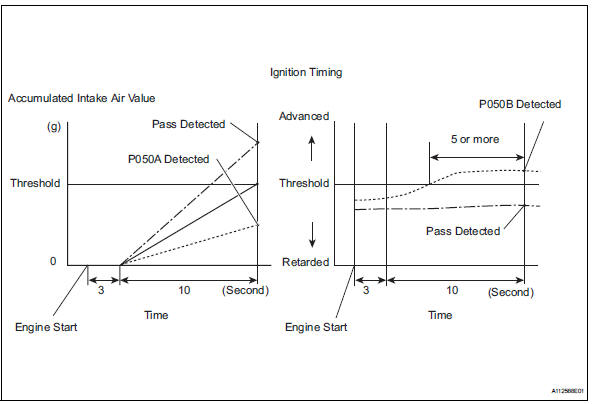
When the engine coolant temperature (ect) is between -10ÂḞc and 50 ÂḞc (14ÂḞf and 122ÂḞf), the ecm calculates the idling intake air amount for 10 seconds, beginning 3 seconds after the engine starts.
When the accumulated value is below the threshold, the ecm interprets this as a malfunction in the idle speed control (isc) system at cold start.
The ecm also monitors the ignition timing at cold start, and judges it to be incorrect when it is advanced to the same value for a warm engine for 5 seconds or more of the 10 second monitoring period.
Example:
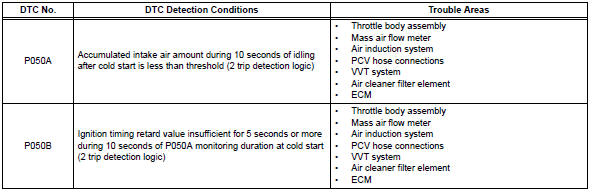
P050a is detected when all conditions below are met (2 trip detection logic).
- The ect is between -10ÂḞc and 50 ÂḞc (14ÂḞf and 122ÂḞf) when the engine starts.
- The engine idles for 13 seconds after engine start.
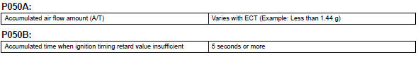
- The accumulated intake air amount is below the threshold.
The ecm sets the dtc and illuminates the mil 13 seconds after the engine is next started.
Notice:
When the negative battery terminal is disconnected during inspection or repairs, the isc learning values are cleared. The isc learning must be performed by warming up the engine and idling for 5 minutes with the ect at 75ÂḞc (167ÂḞf) or more because dtcs cannot be detected with the isc learning values cleared.
Monitor strategy
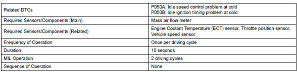
Typical enabling conditions
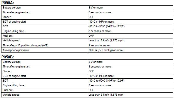
Typical malfunction thresholds
Inspection procedure
Hint:
Read freeze frame data using the intelligent tester. Freeze frame data records the engine condition when malfunctions are detected. When troubleshooting, freeze frame data can help determine if the vehicle was moving or stationary, if the engine was warmed up or not, if the air-fuel ratio was lean or rich, and other data from the time the malfunction occurred.
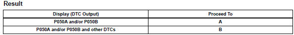
- Check any other dtcs output (in addition to dtc p050a and/or p050b)
- Connect the intelligent tester to the dlc3.
- Turn the ignition switch on.
- Turn the tester on.
- Select the following the menu items: diagnosis / enhanced obd ii / dtc info / current codes.
- Read the dtcs.
Hint:
If any dtcs other than p050a and p050b are output, troubleshoot those dtcs first.


- Read value using intelligent tester (fuel trim)
Hint:
Calculate the total fuel trim values to check the characteristic deviation of the mass air flow meter.
- Connect the intelligent tester to the dlc3.
- Turn the ignition switch on.
- Turn the tester on.
- Select the following menu items: diagnosis / enhanced obd ii / data list / primary / short ft #1 and long ft #1.
- Read the values displayed on the tester.
- Add together the short ft #1 and long ft #1 values to obtain the total fuel trim.
Ok: total of short ft #1 and long ft #1 values is between -20 % and 20 %.


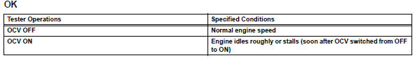
- Perform active test using intelligent tester (operate ocv)
- Connect the intelligent tester to the dlc3.
- Start the engine and turn the tester on.
- Warm up the engine.
- Select the following menu items: diagnosis / enhanced obd ii / active test / vvt ctrl b1
- Check the engine speed while operating the oil control valve (ocv) using the tester.


- Check pcv hose connections
Ok: pcv hose is connected correctly and is not damaged.

- Check air cleaner filter element sub-assembly
- Visually check that the air cleaner filter element is not excessively contaminated with dirt or oil.
Ok: air cleaner filter element is not excessively contaminated with dirt or oil.


- Replace mass air flow meter
 Go to step 15
- Check and repair vvt system
 Go to step 15
- Repair or replace pcv hose
 Go to step 15
- Repair or replace air induction system
 Go to step 15
- Replace air cleaner filter element sub-assembly
 Go to step 15
- Check throttle valve
- Check for deposits around the throttle valve and throttle valve condition.
Ok: no deposits around throttle valve and throttle valve moves smoothly.

- Replace ecm
 Go to step 15
- Repair or replace throttle body assembly
 Go to step 15
- Check whether dtc output recurs (dtc p050a and/or p050b)
Notice:
In this operation, the engine must be cold (the same level as the engine coolant temperature recorded in the freeze frame data).
- Connect the intelligent tester to the dlc3.
- Turn the ignition switch on.
- Turn the tester on.
- Clear dtcs (see page es-35).
- Switch the ecm from normal mode to check mode using the tester (see page es-38).
- Start the engine to idle for a minute.
Ok: stable fast idling.
- Read dtcs.
Ok: no dtc output.

 Idle control system malfunction
Description
The idling speed is controlled by the etcs (electronic throttle control
system). The etcs is comprised
of: 1) the one valve type throttle body; 2) the throttle actuator, which
op ...
 Battery temperature sensor circuit
Description
The battery temperature sensor installed on the battery current sensor
detects battery temperature.
A thermistor is integrated into the battery temperature sensor, and the
...
Other materials:
Automatic transmission
Select the shift position
depending on your purpose
and situation.
Shift position purpose
and functions
P - Parking the vehicle/
starting the engine
R - Reversing
N - Neutral
D - Normal driving*1
S - S mode driving*2
*1:Shifting to the D position allows
the system to select a gear suitable
for ...
On-vehicle inspection
Inspect refrigerant pressure with
manifold gauge set
This method uses a manifold gauge set to locate
problem areas. Read the manifold gauge pressure
when these conditions are established. Test
conditions:
Temperature at the air inlet is 30 to 35ÂḞc (86 to
95ÂḞf).
Engine is ...
Disassembly (2006/01- )
Remove front axle inboard joint boot no. 2
Clamp
One touch type:
using a screwdriver, remove the no. 2 Inboard joint
boot clamp, as shown in the illustration.
Claw engagement type:
using needle-nose pliers, remove the no. 2 Inboard
joint boot clamp, as shown in the illustra ...
