
Toyota RAV4 (XA40) 2013-2018 Service Manual: Turn signal light circuit
Description
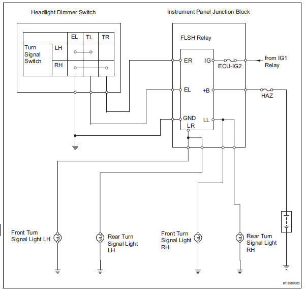
The turn signal flasher relay (marking: flsh) in the main body ecu turns on when it receives signals from the headlight dimmer switch integrated with the turn signal switch, causing the turn signal lights to flash.
Wiring diagram
Inspection procedure
- Check operation of turn signal light
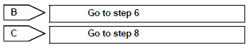
- When the turn signal light switch is operated, check that the appropriate turn signal light flashes.


- Inspect fuse (ecu-ig2, haz)
- Remove the ecu-ig2 fuse from the instrument panel junction block.
- Remove the haz fuse from the engine room no. 1 Relay block.
- Measure the resistance of the fuses.
Standard resistance:
below 1 


- Check wire harness (battery - turn signal flasher relay)
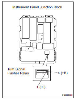
- Disconnect the ib instrument panel junction block connector.
- Remove the turn signal flasher relay from the instrument panel junction block.
- Measure the voltage of the wire harness side connectors.
Standard voltage 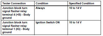


- Inspect headlight dimmer switch
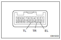
- Remove the headlight dimmer switch.
- Inspect the turn signal switch.
- Measure the resistance of the switch.
Standard resistance 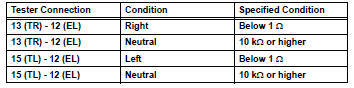


- Check wire harness (headlight dimmer switch - instrument panel junction block)
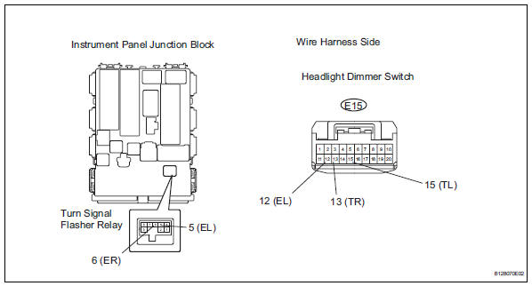
- Remove the turn signal flasher relay.
- Disconnect the e15 headlight dimmer switch connector.
- Measure the resistance of the wire harness side connectors and junction block.
Standard resistance 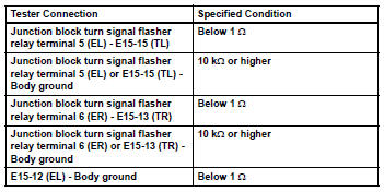


Replace turn signal flasher relay
- Inspect front turn signal light
- Remove the front turn signal light.
- Connect the positive (+) lead from the battery to terminal 1 and the negative (-) lead to terminal 2, then check that the light comes on.
Ok: light comes on.


- Check wire harness (instrument panel junction block - front turn signal light)
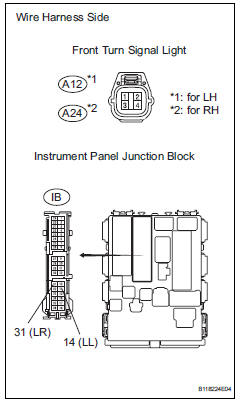
- Disconnect the a12 and a24 front turn signal light connectors.
- Disconnect the ib instrument panel junction block connector.
- Measure the resistance of the wire harness side connectors.
Standard resistance 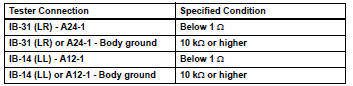


Repair or replace harness and connector (front turn signal light - body ground)
- Inspect rear turn signal light
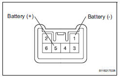
- Remove the rear combinationl light.
- Connect the positive (+) lead from the battery to terminal 5 and the negative (-) lead to terminal 1, then check that the light comes on.
Ok: light comes on.


- Check wire harness (instrument panel junction block - rear turn signal light)
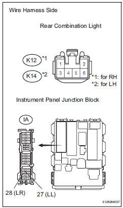
- Disconnect the k12 and k14 rear combination light connectors.
- Disconnect the ia instrument panel junction block connector.
- Measure the resistance of the wire harness side connectors.
Standard resistance 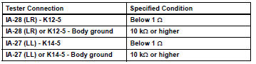


Repair or replace harness and connector (rear turn signal light - body ground)
 Front fog light circuit
Description
The main body ecu controls the front fog light relay (marking: fr fog) when a
signal is received from
the headlight dimmer switch.
Wiring diagram
Inspection procedure
Perform ...
 Hazard warning switch circuit
Description
When the hazard warning signal switch is turned on, the turn signal flasher
relay (marking: flsh) in the
main body ecu turns on to flash the hazard warning signal lights.
Wiring diagr ...
Other materials:
Lda
(lane departure alert)
Summary of function
While driving on a road that has lane markers, this system recognizes
the lane markers using a camera as a sensor to alert the driver when
the vehicle deviates from its lane.
If the system judges that the vehicle may deviate from its lane, it alerts
the driver using beepin ...
Stuck in deceleration sensor
Description
The skid control ecu receives signals from the yaw rate and deceleration
sensor via the can
communication system.
The yaw rate sensor has a built-in deceleration sensor and detects the vehicle's
condition using 2 circuits
(gl1: g sensor 1, gl2: g sensor 2).
If there is t ...
Cleaning the Digital Rearview
Mirror
â– Cleaning the mirror surface
If the mirror surface is dirty, the
image on the display may be difficult
to see.
Clean the mirror surface gently
using a soft dry cloth.
â– Cleaning the camera
If the camera lens is dirty, the
displayed image may not be
clear. In this case, clean it with a
soft clo ...
