Toyota RAV4 (XA40) 2013-2018 Service Manual: Disassembly (2006/01- )
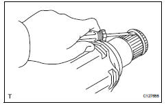
- Remove front axle inboard joint boot no. 2 Clamp
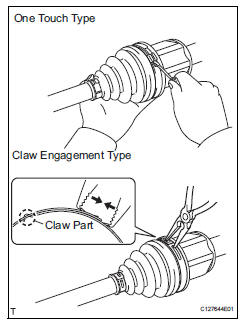
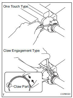
- One touch type: using a screwdriver, remove the no. 2 Inboard joint boot clamp, as shown in the illustration.
- Claw engagement type: using needle-nose pliers, remove the no. 2 Inboard joint boot clamp, as shown in the illustration.
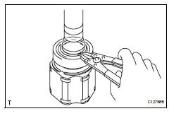
- Remove front axle inboard joint boot clamp
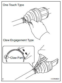
- One touch type: using a screwdriver, remove the inboard joint boot clamp, as shown in the illustration.
- Claw engagement type: using needle-nose pliers, remove the inboard joint boot clamp, as shown in the illustration.
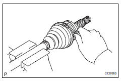
- Remove front axle inboard joint boot
- Remove the boot from the inboard joint.
- Remove front drive inboard joint assembly lh
- Remove any old grease from the inboard joint.
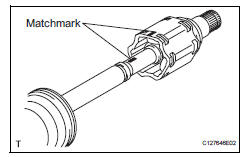
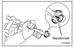
- Put matchmarks on the inboard joint and outboard joint shaft.
Notice:
Do not punch the marks.
- Remove the inboard joint from the outboard joint shaft.
- Using a snap ring expander, remove the shaft snap ring.
- Put matchmarks on the outboard joint shaft and tripod joint.
Notice:
Do not punch the marks.
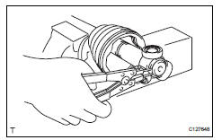
- Using a brass bar and hammer, tap out the tripod joint from the outboard joint shaft.
Notice:
Do not tap the rollers.
- Remove the inboard joint boot.
- Remove front drive shaft inboard joint assembly rh
Hint:
Use the same procedures described for the lh side.
- Remove front drive shaft damper clamp lh
- One touch type: using a screwdriver, remove the drive shaft damper clamp, as shown in the illustration.
- Claw engagement type: using needle-nose pliers, remove the drive shaft damper clamp, as shown in the illustration.
- Remove front drive shaft damper lh
- Remove the front drive shaft damper
- Remove front drive shaft damper clamp rh
Hint:
Use the same procedures described for the lh side.
- Remove front drive shaft damper rh
Hint:
Use the same procedures described for the lh side.
- Remove front axle outboard joint boot no. 2 Clamp
- Using a screwdriver, remove the no. 2 Outboard joint boot clamp, as shown in the illustration.
- Remove front axle outboard joint boot clamp
- Using a screwdriver, remove the outboard joint boot clamp, as shown in the illustration.
- Remove front axle outboard joint boot
- Remove the outboard joint boot from the outboard joint shaft.
- Remove any old grease from the outboard joint.
- Remove front drive shaft hole snap ring lh
- Using a screwdriver, remove the hole snap ring.
- Remove front drive shaft dust cover lh
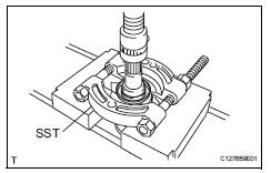
- Using sst and a press, press out the front drive shaft dust cover.
Sst 09950-00020
Notice:
Be careful not to drop the inboard joint.
- Remove front drive shaft dust cover rh
Hint:
Use the same procedures described for the lh side.
- Remove front drive shaft bearing (for rh)
- Using a snap ring expander, remove the drive shaft hole snap ring.

- Using sst and a press, press out the drive shaft bearing.
Sst 09527-10011
- Remove the bearing bracket snap ring.
 Disassembly (2005/11-2006/01)
Remove front axle inboard joint boot no. 2
Clamp lh
One touch type:
Using a screwdriver, remove the no. 2 Inboard
joint boot clamp, as shown in the illustration.
Claw eng ...
 Reassembly (2005/11-2006/01)
Install front drive shaft bearing
Using sst and a press, press in the drive shaft
bearing to the inboard joint rh.
Sst 09527-10011, 09710-04081
Notice:
The bearing should be instal ...
Other materials:
Adjusting the settings manually
To adjust the fan speed, press
on
to increase the fan
speed and to
decrease the fan speed.
Press to turn the fan off.
To adjust the temperature setting, turn
clockwise to
increases the temperature and turn
counterclockwise to
...
Headlight relay circuit
Description
When the light control switch, located on the headlight dimmer switch, is
turned to the head position, the
head relay illuminates the headlights.
Wiring diagram
Inspection procedure
Perform active test by intelligent tester (headlight)
Connect the intelligent tester ( ...
Blower resistor
On-vehicle inspection
Inspect blower motor control
Measure the resistance of the blower resistor.
Standard resistance
If the resistance is not as specified, replace the
blower motor control. ...
