Toyota RAV4 (XA40) 2013-2018 Service Manual: Disassembly (2005/11-2006/01)
- Remove front axle inboard joint boot no. 2 Clamp lh
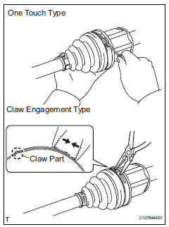
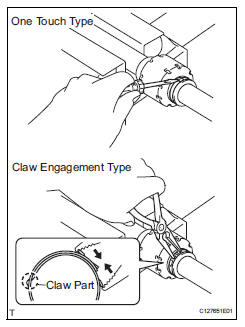
- One touch type:
- Using a screwdriver, remove the no. 2 Inboard joint boot clamp, as shown in the illustration.
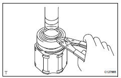
- Claw engagement type:
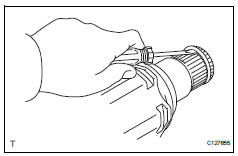
Using needle-nose pliers, remove the no. 2 Inboard joint boot clamp, as shown in the illustration.
- Remove front axle inboard joint boot no.
2 Clamp rh
Hint:
Using needle-nose pliers, remove the no. 2 Inboard joint boot clamp, as shown in the illustration.
- Remove front axle inboard joint boot clamp lh
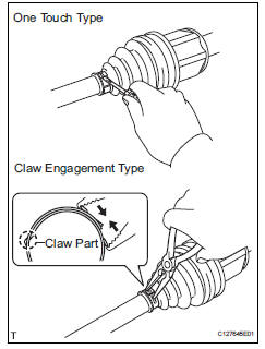
- One touch type:
- Using a screwdriver, remove the inboard joint boot clamp, as shown in the illustration.
- Claw engagement type:
Using needle-nose pliers, remove the inboard joint boot clamp, as shown in the illustration.
- Remove front axle inboard joint boot clamp rh
Hint:
Use the same procedures described for the lh side.
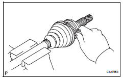
- Remove front axle inboard joint boot
- Remove the boot from the inboard joint.
- Remove front drive inboard joint assembly lh
- Remove any old grease from the inboard joint.
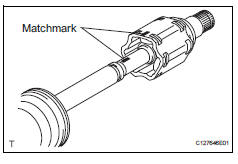
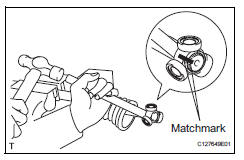
- Put matchmarks on the inboard joint and outboard joint shaft.
Notice:
Do not punch the marks.
- Remove the inboard joint from the outboard joint shaft.
- Using a snap ring expander, remove the shaft snap ring.
- Put matchmarks on the outboard joint shaft and tripod joint.
Notice:
Do not punch the marks.
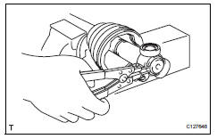
- Using a brass bar and hammer, tap out the tripod joint from the outboard joint shaft.
Notice:
Do not tap the rollers.
- Remove the inboard joint boot.
- Remove front drive shaft damper clamp lh
- One touch type:
- Using a screwdriver, remove the drive shaft damper clamp, as shown in the illustration.
- Claw engagement type:
- Using needle-nose pliers, remove the drive shaft damper clamp, as shown in the illustration.
- Remove front drive shaft damper lh
- Remove the front drive shaft damper.
- Remove front drive shaft damper clamp rh
Hint:
Use the same procedures described for the lh side.
- Remove front drive shaft damper rh
Hint:
Use the same procedures described for the lh side.
- Remove front axle outboard joint boot no. 2 Clamp lh
- Using a screwdriver, remove the no. 2 Outboard joint boot clamp, as shown in the illustration.
- Remove front axle outboard joint boot clamp lh
- Using a screwdriver, remove the outboard joint boot clamp, as shown in the illustration.
- Remove front axle outboard joint boot
- Remove the outboard joint boot from the outboard joint shaft.
- Remove any old grease from the outboard joint.
- Remove front drive shaft hole snap ring lh
- Using a screwdriver, remove the hole snap ring.
- Remove front drive shaft dust cover lh
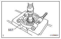
- Using sst and a press, press out the front drive shaft dust cover.
Sst 09950-00020
Notice:
Be careful not to drop the inboard joint
- Remove front drive shaft dust cover rh
- Using a press, press out the drive shaft dust cover.
- Remove front drive shaft bearing
- Using a snap ring expander, remove the drive shaft hole snap ring.
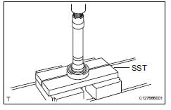
- Using sst and a press, press out the drive shaft bearing.
Sst 09527-10011
- Remove the snap ring.
 Removal
(2006/01- )
Removal
(2006/01- )
Remove front wheel
Drain automatic transaxle fluid
Drain the automatic transaxle fluid for u140f (see
page ax-147).
Drain the automatic transaxle fluid for u241e (see
page ax-146).
...
 Disassembly (2006/01- )
Remove front axle inboard joint boot no. 2
Clamp
One touch type:
using a screwdriver, remove the no. 2 Inboard joint
boot clamp, as shown in the illustration.
Claw engagement typ ...
Other materials:
Yaw rate sensor communication stop mode
Description
Wiring diagram
Inspection procedure
Notice:
Turn the ignition switch off before measuring the resistances of the
main wire and the branch
wire.
After the ignition switch is turned off, check that the key reminder
warning system and light
reminder warning system ...
Check mode procedure
Check mode (signal check)
Connect the intelligent tester (with can vim) to the
dlc3.
Turn the ignition switch on.
Select the "signal check", and continue
checking with the intelligent tester.
Notice:
Select the "signal check" from the "dtc
check&quo ...
Opening/closing the back
door (vehicles with power
back door)
â– Using the wireless remote
control
Press and hold the switch.
The power back door automatically
opens/closes.
Pressing the switch while the power
back door is opening/closing stops
the operation. When the switch is
pressed and held again during the
halted operation, the back door will
perform t ...
