Toyota RAV4 (XA40) 2013-2018 Service Manual: Battery current sensor circuit
Description
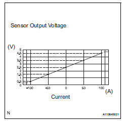
The battery current sensor installed on the positive (+) battery terminal detects the amount of current supplied from the generator.
The battery current sensor changes current to voltage (at the positive (+) battery terminal) and sends it to the ecm. The ecm controls the voltage of the generator based on the signals from the battery current sensor.
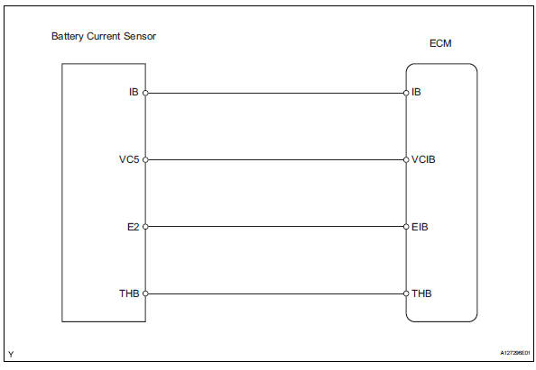
Wiring diagram
Inspection procedure
Hint:
- If different dtcs that are related to a different system are output simultaneously while terminal e2 is used as a ground terminal, terminal e2 may be open.
- Read freeze frame data using the intelligent tester. Freeze frame data records the engine conditions when malfunctions are detected. When troubleshooting, freeze frame data can help determine if the vehicle was running or stopped, if the engine was warmed up or not, if the air-fuel ratio was lean or rich, and other data from the time the malfunction occurred.
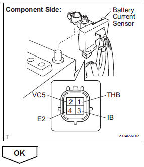
- Inspect battery current sensor assembly
- Disconnect the b29 battery current sensor connector.
- Measure the resistance of the battery current sensor.
Standard resistance 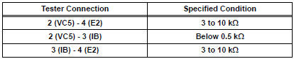
Hint:
The resistance differs according to the tester type.
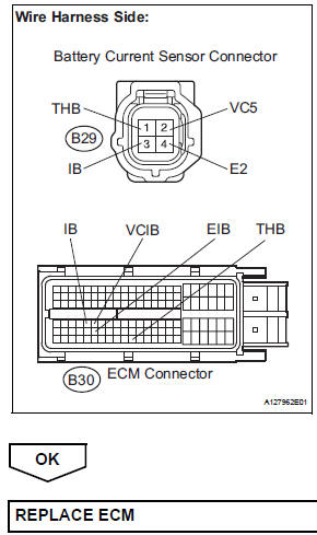
- Check harness and connector (battery current sensor - ecm)
- Disconnect the b29 battery current sensor connector.
- Disconnect the b30 ecm connectors.
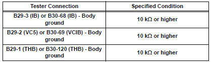
- Measure the resistance of the wire harness side connectors.
Standard resistance (check for open)
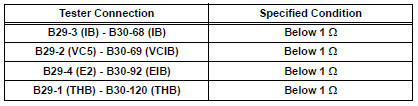
Standard resistance (check for short)
 Brake switch "b" circuit high
Description
The purpose of this circuit is to prevent the engine from stalling while
driving in the lock-up condition when
the brakes are suddenly applied.
When the brake pedal is depressed ...
 Deterioration of battery
Description
The ecm determines the battery power according to the voltage of the batt
terminal while the engine is
running (not cranking).
Inspection procedure
Inspect battery
Inspe ...
Other materials:
Defogging the windshield
Press .
The dehumidification function
operates and fan speed increases.
Set the outside/recirculated air
mode button to outside air mode if
the recirculated air mode is used.
(It may switch automatically.)
To defog the windshield and the
side windows early, turn the air
flow and t ...
Playing back mp3 and wma discs
Power
Volume
Cd eject
Selecting a file or displaying
folder list
Searching playback
Next commands, random play
or back button
Repeat play
Fast-forwarding, rewinding or
selecting a folder
Changing the audio source/
playback
Playback/pause
Previous commands
Selecti ...
Steering column assembly
Components
Removal
Caution:
Some of these service operations affect the srs airbag
system. Read the precautionary notices concerning the
srs airbag system before servicing the steering column
(see page rs-1).
Place front wheels facing straight ahead
Disconnect cab ...
