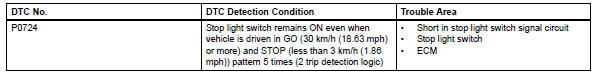
Toyota RAV4 (XA40) 2013-2018 Service Manual: Brake switch "b" circuit high
![]()
Description
The purpose of this circuit is to prevent the engine from stalling while driving in the lock-up condition when the brakes are suddenly applied.
When the brake pedal is depressed, this switch sends a signal to the ecm. Then the ecm cancels the operation of the lock-up clutch while braking is in progress.
Monitor description
This dtc indicates that the stop light switch remains on. When the stop light switch remains on during go and stop driving, the ecm interprets this as a fault in the stop light switch. Then the mil illuminates and the ecm stores the dtc. The vehicle must go (30 km/h (18.63 Mph) or more) and stop (less than 3 km/h (1.86 Mph)) 5 times for 2 driving cycles in order for the dtc to be output.
Monitor strategy
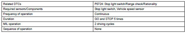
Typical enabling conditions
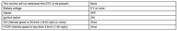
Typical malfunction thresholds
![]()
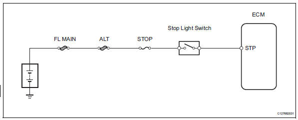
Wiring diagram
Inspection procedure
Hint:
Using the intelligent tester's data list allows switch, sensor, actuator and other item values to be read without removing any parts. Reading the data list early in troubleshooting is one way to save time.
Notice:
In the table below, the values listed under "normal condition" are reference values. Do not depend solely on these reference values when deciding whether a part is faulty or not.
- Warm up the engine.
- Turn the ignition switch off.
- Connect the intelligent tester to the can vim. Then connect the can vim to the dlc3.
- Turn the ignition switch on
- Turn the intelligent tester on.
- Enter the following menus: diagnosis / enhanced obd ii / data list.
- Follow the instructions on the tester and read the data list.
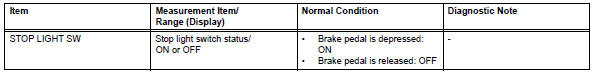
- Inspect stop light switch
- Remove the a3 stop light switch.
- Measure the resistance of the switch.
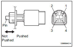
Standard resistance 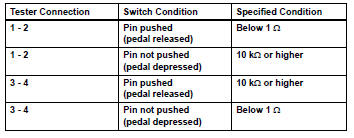


- Check wire harness (ecm - battery)
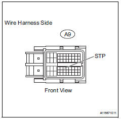
- Measure the voltage of the wire harness side connector.
Standard voltage 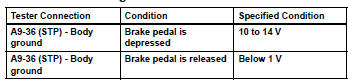
 Vin not programmed or mismatch - ecm / pcm
Description
Dtc p0630 is set when the vehicle identification number (vin) is not stored
in the engine control module
(ecm) or the input vin is incorrect. Input the vin with the intelligent tester. ...
 Battery current sensor circuit
Description
The battery current sensor installed on the positive (+) battery terminal
detects the amount of current
supplied from the generator.
The battery current sensor changes curre ...
Other materials:
Floor shift assembly
Components
Removal
Disconnect cable from negative battery
terminal
Caution:
Wait at least 90 seconds after disconnecting the
cable from the negative (-) battery terminal to
prevent airbag and seat belt pretensioner activation.
Remove shift lever knob sub-assembly
Remove re ...
Customize parameters
Customizing function with intelligent
tester (reference)
Hint:
The following item can be customized.
Notice:
When the customer requests a change in a
function, first make sure that the function can be
customized.
Make a note of the current settings before
customizing.
When tr ...
System description
Engine immobiliser system description
The engine immobiliser system is designed to prevent
the vehicle from being stolen. This system uses a
transponder key ecu that stores the key codes of
authorized ignition keys. If an attempt is made to start
the engine using an unauthorized key, the e ...
