Toyota RAV4 (XA40) 2013-2018 Service Manual: Brake pedal load sensing switch
Description
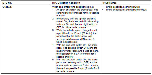
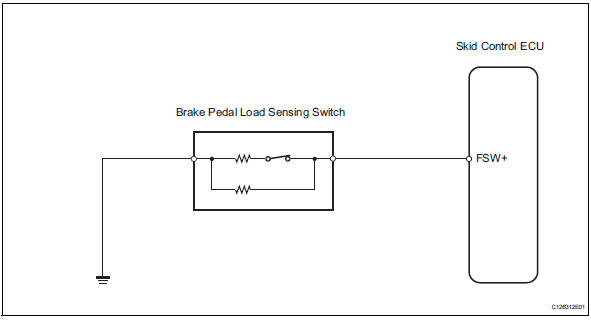
The brake pedal load sensing switch is turned on when the brake pedal is depressed with force exceeding a predetermined level.
The skid control ecu detects if the brake pedal is depressed or not via this circuit.
Wiring diagram
Inspection procedure
Notice:
When replacing the brake actuator assembly, perform zero point calibration (see page bc-24).
Hint:
If dtc c1249/49 is output, repair it before repairing dtc c1267/67 based on the flowchart below.
- Read value of intelligent tester (brake pedal load sensing switch)
- Check the data list for proper functioning of the brake pedal load sensing switch.
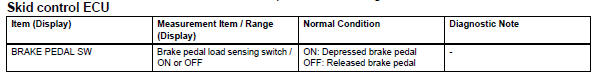
Ok: on (brake pedal is depressed) appears on the screen.


- Inspect brake pedal load sensing switch
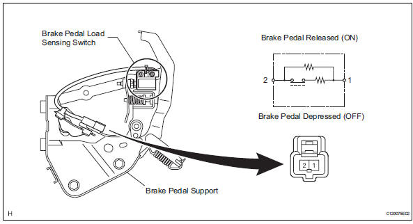
Notice:
- Do not remove the brake pedal load sensing switch from the brake pedal.
- When there is a malfunction in the brake pedal load sensing switch, replace the brake pedal.
- Turn the ignition switch off.
- Disconnect the brake pedal load sensing switch connector.
- Measure the resistance of the switch.
Standard resistance


- Check wire harness (skid control ecu - brake pedal load sensing switch)
- Disconnect the a19 ecu connector.
- Measure the resistance of the wire harness side connectors.
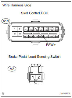
Standard resistance 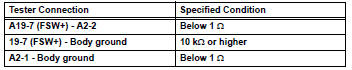

- Reconfirm dtc
- Clear the dtc (see page bc-47).
- Check if the same dtc is recorded (see page bc-47).
Result 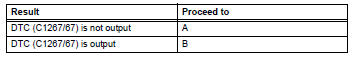

Use simulation method to check
 Open in pump motor circuit
Description
The motor relay drives the pump motor based on a signal from the skid control
ecu.
Wiring diagram
Refer to dtc c0273/13, c0274/14, c1361/91 (see page bc-79).
Inspection proce ...
 Steering angle sensor zero point malfunction
Description
The skid control ecu learns the steering sensor zero point every time the
ignition switch is turned on and
the vehicle is driven at 35 km/h (22 mph) or more for approximately 5 sec ...
Other materials:
Removal
Disconnect cable from negative battery
terminal
Caution:
Wait at least 90 seconds after disconnecting the
cable from the negative (-) battery terminal to
prevent airbag and seat belt pretensioner activation.
Remove rear door scuff plate rh (see page
ir-29)
Remove package tray trim ...
Axle system
Problem symptoms table
Hint:
Use the table below to help determine the cause of the
problem symptom. The potential causes of the symptoms are
listed in order of probability in the "suspected area" column of
the table. Check each symptom by checking the suspected
areas in the order th ...
Passenger side buckle switch circuit malfunction
Description
The passenger side buckle switch circuit consists of the occupant
classification ecu and the front seat
inner belt rh.
Dtc b1771 is recorded when a malfunction is detected in the passenger side
buckle switch circuit.
Troubleshoot dtc b1771 first when dtcs b1771 and b1795 ...
