Toyota RAV4 (XA40) 2013-2018 Service Manual: Camshaft position correlation (bank 1 sensor a)
Dtc
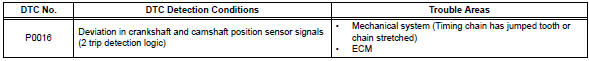
P0016 P0016 crankshaft position - camshaft position correlation (bank 1 sensor a)
Description
In the vvt (variable valve timing) system, the appropriate intake valve open and close timing is controlled by the ecm. The ecm performs intake valve control by performing the following: 1) controlling the camshaft and camshaft timing oil control valve, and operating the camshaft timing gear; and 2) changing the relative positions of the gaps between the camshaft and crankshaft
Monitor description
The ecm optimizes the valve timing by using the vvt (variable valve timing) system to control the intake camshaft. The vvt system includes the ecm, the oil control valve (ocv) and the vvt controller.
The ecm sends a target duty-cycle control signal to the ocv. This control signal regulates the oil pressure supplied to the vvt controller. The vvt controller can advance or retard the intake camshaft.
The ecm calibrates the intake valve timing by setting the intake camshaft to the most retarded angle while the engine is idling. The ecm closes the ocv to retard the cam. The ecm stores this value as the vvt learning value. When the difference between the target and actual intake valve timings is 5°ca (crankshaft angle) or less, the ecm stores it.
If the vvt learning value matches the following conditions, the ecm determines the existence of a malfunction in the vvt system, and sets the dtc.
- Vvt learning value: less than 25°ca, or more than 51°ca.
- Above condition continues for 18 seconds or more.
This dtc indicates that the angle between the intake camshaft and the crankshaft is incorrect due to factors such as the timing chain having jumped a tooth.
This monitor begins to run after the engine has idled for 5 minutes.
Monitor strategy
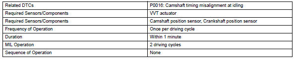
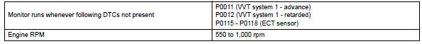
Typical enabling conditions
Typical malfunction thresholds

Wiring diagram
Refer to dtc p0335 (see page es-172).
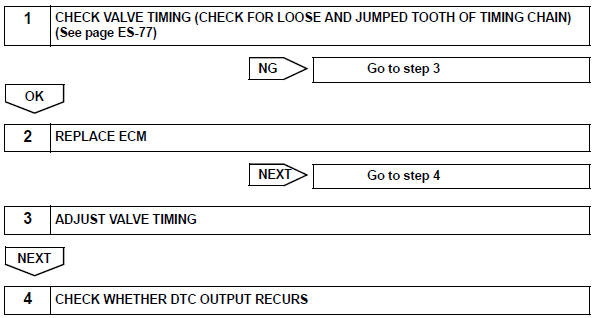
Inspection procedure
Hint:
Read freeze frame data using the intelligent tester. Freeze frame data records the engine condition when malfunctions are detected. When troubleshooting, freeze frame data can help determine if the vehicle was moving or stationary, if the engine was warmed up or not, if the air-fuel ratio was lean or rich, and other data from the time the malfunction occurred.
Notice:
After replacing the ecm or adjusting intake valve timing, confirm that the dtc output does not recur.
- Connect the intelligent tester to the dlc3.
- Turn the ignition switch on.
- Turn the tester on.
- Clear dtcs (see page es-35).
- Switch the ecm from normal mode to check mode using the tester (see page es-38).
- Start the engine and warm it up.
- Allow the engine to idle for 1 minute or more, and then drive the vehicle for 1 minute or more.
- Confirm that no dtc is set, using the tester.
Ok: no dtc output

 Camshaft position "A"
Dtc P0011 Camshaft position
"a" - timing over-advanced or system performance (bank 1)
Dtc P0012 Camshaft
position "a" - timing over-retarded (bank 1)
Description
The v ...
 Oxygen (a/f) sensor heater control circuit
Hint:
Although the dtc titles say oxygen sensor, these dtcs relate to the
air-fuel ratio (a/f) sensor.
Sensor 1 refers to the sensor mounted in front of the three-way
catalytic convert ...
Other materials:
On-vehicle inspection
Check ignition coil assembly and perform spark test
Notice:
in this section, the terms "cold" and "hot" refer to
the temperature of the coils. "Cold" means
approximately -10 to 50°c (14 to 122°f). "Hot" means
approximately 50 to 100°c (122 to 212 ...
Inspection
Inspect camshaft timing oil control valve
assembly
Measure the resistance of the oil control valve.
Standard resistance
If the result is not as specified, replace the oil control
valve assembly.
Check the operation.
Apply battery voltage across the terminals and
chec ...
Pressure control solenoid "A " performance (shift solenoid valve sl1)
Description
The ecm uses signals from the vehicle speed sensor to detect the actual gear
position (1st, 2nd, 3rd or
o/d gear).
Then the ecm compares the actual gear with the shift schedule in the ecm memory
to detect mechanical
problems of the shift solenoid valves, valve body or automatic ...
