Toyota RAV4 (XA40) 2013-2018 Service Manual: Compressor solenoid circuit (2006/01- )

Description
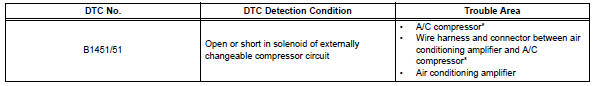
In this circuit, the compressor receives a refrigerant compression demand signal from the air conditioning amplifier. Based on this signal, the compressor changes the degree of refrigerant compression.
Hint:
*: Compressor and pulley for 2az-fe, compressor and magnetic clutch for 2gr-fe
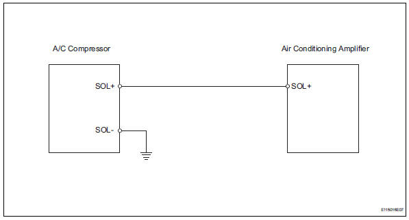
Wiring diagram
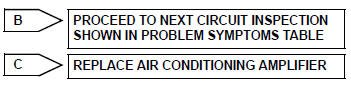
Inspection procedure
- Read value of intelligent tester (reg ctrl currnt)
- Connect the intelligent tester (with can vim) to the dlc3.
- Turn the ignition switch on and turn the intelligent tester main switch on.
- Select the items below in the data list, and read the value displayed on the intelligent tester.
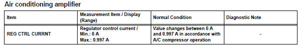
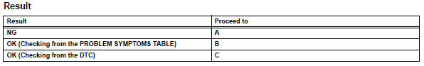
Ok: the display is as specified in the normal condition column.

- Inspect a/c compressor
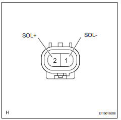
- Disconnect the a/c compressor clutch connector.
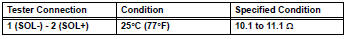
- Measure the resistance of the connector.
Standard resistance

- Check wire harness (a/c compressor - air conditioning amplifier)
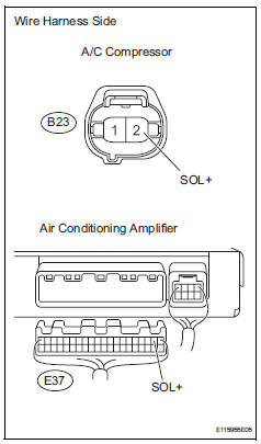
- Disconnect the b23 a/c compressor connector.
- Disconnect the e37 amplifier connector.
- Measure the resistance of the wire harness side connectors.
Standard resistance
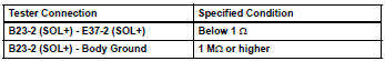

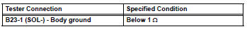
- Check wire harness (a/c compressor - body ground)
- Disconnect the b23 a/c compressor connector.
- Measure the resistance of the wire harness side connector.
Standard resistance

Replace air conditioning amplifier
 Compressor solenoid circuit (2005/11-2006/01)
Description
In this circuit, the compressor receives a refrigerant compression demand
signal from the air conditioning
amplifier. Based on this signal, the compressor changes the degree of
r ...
 Bus ic communication malfunction
Description
The air conditioning harness connects the air conditioning amplifier and the
servos. The air conditioning
amplifier supplies power and sends operation instructions to each servo th ...
Other materials:
Check mode procedure
Hint:
Intelligent tester only:
compared to normal mode, check mode is more sensitive to
malfunctions. Therefore, check mode can detect the
malfunctions that cannot be detected by normal mode.
Notice:
All the stored dtcs and freeze frame data are erased if:
The ecm is changed from normal mo ...
Towing related terms
‚ñÝ GCWR (Gross Combination
Weight Rating)
The maximum allowable gross
combination weight. The gross combination weight is the sum
of the total vehicle weight
(including the occupants, cargo
and any optional equipment
installed on the vehicle) and the
weight of the trailer being towed
(including the ...
Customizing the startup and screen off images (if equipped)
An image can be copied from a usb memory and used as the startup
and screen off images.
When the engine switch is in the “acc” or “on” position (vehicles
without a smart key system) or accessory or ignition on mode
(vehicles with a smart key system), the initial screen will be displaye ...
