Toyota RAV4 (XA40) 2013-2018 Service Manual: Bus ic communication malfunction
![]()
Description
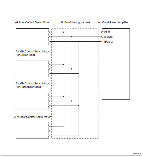
The air conditioning harness connects the air conditioning amplifier and the servos. The air conditioning amplifier supplies power and sends operation instructions to each servo through the air conditioning harness. Each servo sends damper position information to the air conditioning amplifier.

Wiring diagram
Inspection procedure
- Check air conditioning amplifier
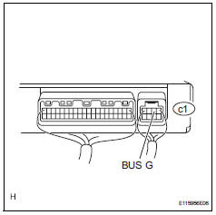
- Remove the air conditioning amplifier with its connectors still connected.
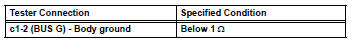
- Measure the resistance of the wire harness side connector.
Standard resistance

- Check air conditioning amplifier
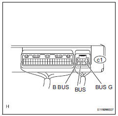
- Remove the air conditioning amplifier with its connectors still connected.
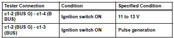
- Measure the voltage of the wire harness side connector.
Standard voltage


Replace air conditioning harness assembly
 Compressor solenoid circuit (2006/01- )
Description
In this circuit, the compressor receives a refrigerant compression demand
signal from the air conditioning
amplifier. Based on this signal, the compressor changes the degree of
r ...
 Multiplex communication circuit
Description
The air conditioning amplifier communicates data with the ecm and combination
meter through the can
communication system.
Wiring diagram
Inspection procedure
Check dt ...
Other materials:
Operating a usb memory
Connecting a usb memory enables you to enjoy music from the
vehicle speakers.
Connecting a usb memory
Open the cover and connect
a usb memory.
Turn on the power of the usb
memory if it is not turned on.
Press the “media” button repeatedly until “usb” is displayed.
Cont ...
Torque sensor
Description
The torque sensor converts the rotation torque input from the steering wheel
into electric signals and
sends them to the power steering ecu.
Wiring diagram
Inspection procedure
Check connector connection condition (torque sensor - ecu)
Check the installation c ...
Parts location
System diagram
...
