Toyota RAV4 (XA40) 2013-2018 Service Manual: Sliding roof control switch circuit
Description
If either the sliding function or tilt function does not operate, there may be a malfunction in the sliding roof control switch circuit.
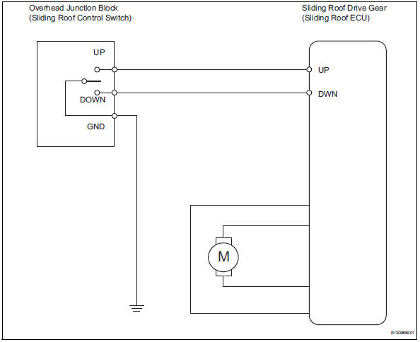
Wiring diagram
Inspection procedure
- Perform active test by intelligent tester (sliding roof operation)
- Select the active test, use the intelligent tester to generate a control command, and then check that the sliding roof operates normally.
Sliding roof ecu
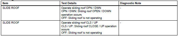
Ok: sliding roof operates normally.

- Read value of intelligent tester (sliding roof control switch)
- Use the data list to check if the sliding roof switch is functioning properly.
Sliding roof ecu
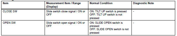
Ok: when the switch is operating, the intelligent tester should display as shown in the table.

- Check wire harness (overhead junction block - drive gear and body ground)
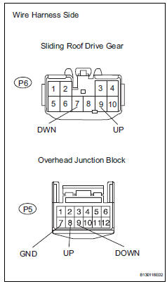
- Disconnect the p5 junction block connector.
- Disconnect the p6 drive gear connector
- Measure the resistance of the wire harness side connectors.
Standard resistance 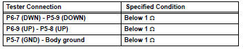

Replace overhead junction block
 Position initialization incomplete
Description
This dtc is output when the sliding roof drive gear (sliding roof ecu) has
not been initialized.
Wiring diagram
Refer to dtc b2341 (see page rf-11).
Inspection procedure
...

Other materials:
System description
System description
Hint:
The skid control ecu forms a single unit with the abs
and traction actuator.
Abs (anti-lock brake system):
the abs helps prevent the wheels from locking
when the brakes are applied firmly or on a slippery
surface.
Operation description:
the skid ...
Front passenger side rear airbag sensor circuit malfunction
Description
The rear airbag sensor rh consists of parts including the diagnostic circuit
and the lateral deceleration
sensor.
When the center airbag sensor receives signals from the lateral deceleration
sensor, it determines
whether or not the srs should be activated.
Dtc b1635/24 i ...
Listening to an ipod
Connecting an ipod enables you to enjoy music from the vehicle
speakers.
Select “ipod” on the audio source selection screen.
When the ipod connected to the system includes ipod video, the
system can only output the sound by selecting the browse
screen.
Connecting an ipod
Audio control ...
