Toyota RAV4 (XA40) 2013-2018 Service Manual: Compressor solenoid circuit (2006/01- )

Description
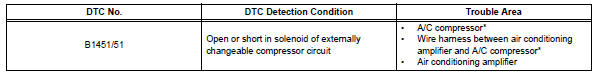
In this circuit, the compressor receives a refrigerant compression demand signal from the air conditioning amplifier. Based on this signal, the compressor changes the degree of refrigerant compression.
Hint:
*: Compressor and pulley for 2az-fe, compressor and magnetic clutch for 2gr-fe
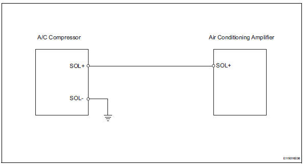
Wiring diagram
Inspection procedure
- Read value of intelligent tester (reg ctrl currnt)
- Connect the intelligent tester (with can vim) to the dlc3.
- Turn the ignition switch on and turn the intelligent tester main switch on.
- Select the items below in the data list, and read the value displayed on the intelligent tester.
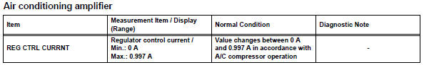
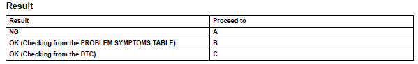
Ok: the display is as specified in the normal condition column.

- Inspect a/c compressor
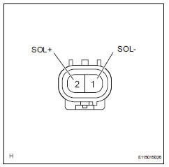
- Disconnect the a/c compressor connector.
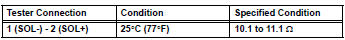
- Measure the resistance of the connector.
Standard resistance

- Check wire harness (a/c compressor - air conditioning amplifier)
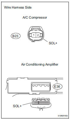
- Disconnect the b23 a/c compressor connector.
- Disconnect the e36 amplifier connector.
- Measure the resistance of the wire harness side connectors.
Standard resistance 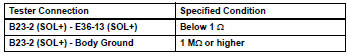

- Check wire harness (a/c compressor - body ground)
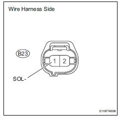
- Disconnect the b23 a/c compressor connector.
- Measure the resistance of the wire harness side connector.
Standard resistance 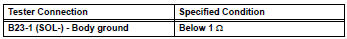


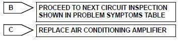
Replace air conditioning amplifier
 Compressor solenoid circuit (2005/11-2006/01)
Description
In this circuit, the compressor receives a refrigerant compression demand
signal from the air conditioning
amplifier. Based on this signal, the compressor changes the degree of
r ...
 Multiplex communication circuit
Description
The air conditioning amplifier communicates data with the ecm and combination
meter through the can
communication system.
Wiring diagram
Inspection procedure
Check dt ...
Other materials:
Intuitive parking assist
The distance from your vehicle to nearby obstacles when parallel
parking or maneuvering into a garage is measured by the
sensors and communicated via the indicator and a buzzer.
Always check the surrounding area when using this system.
Types of sensors
Rear corner sensors
Rear center sen ...
How to proceed with troubleshooting
Hint:
Use the procedure to troubleshoot the power door lock
control system.
*: Use the intelligent tester.
Vehicle brought to workshop
Inspect battery voltage
Standard voltage:
11 to 14 v
If the voltage is below 11 v, recharge or replace the battery
before proceeding.
...
System description
Brief description
The can (controller area network) is a serial data
communication system for real time application. It is
a vehicle multiplex communication system which
has a high communication speed (500 kbps) and
the ability to detect malfunctions.
By pairing the canh and canl ...
