Toyota RAV4 (XA40) 2013-2018 Owners Manual: Connecting a bluetoothÂź device
Up to 5 bluetoothÂź devices (phones (hfp) and audio players (avp)) can be registered.
If more than 1 bluetoothÂź device has been registered, select which device to connect to.
- Press the âsetupâ button.
- Select âbluetooth*â.
*: Bluetooth is a registered trademark of bluetooth sig, inc.
- Select the device to be connected.
Supported profile icons will be displayed.
- Phone
- Audio player
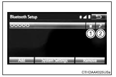
Supported profile icons for currently connected devices will illuminate.
Dimmed icons can be selected to connect to the function directly.
Auto connection
To turn auto connection mode on, set âbluetooth* powerâ to on.
*: Bluetooth is a registered trademark of bluetooth sig, inc.
When you register a phone, auto connection will be activated. Always set it to this mode and leave the bluetoothÂź phone in a place where a connection can be established.
When the engine switch is turned to the âaccâ or âonâ position (vehicles without a smart key system) or accessory or ignition on mode (vehicles with a smart key system), the system will search for a nearby cellular phone you have registered.
Next, the system automatically connects with the most recent of the phones connected to in the past. Then, the connection result is displayed.
Manual connection
When auto connection has failed or âbluetooth* powerâ is turned off, you must connect the bluetoothÂź device manually.
*: Bluetooth is a registered trademark of bluetooth sig, inc.
Follow the steps in âconnecting a bluetoothÂź deviceâ from 1.
Connecting a bluetoothÂź audio player
Registering an additional device
- Select âselect deviceâ on the bluetoothÂź audio control screen.
- For more information
Selecting a registered device
- Select âselect deviceâ on the bluetoothÂź audio control screen.
- For more information
Reconnecting a bluetoothÂź phone
If the system cannot connect due to poor signal strength with the engine switch in the âaccâ or âonâ position (vehicles without a smart key system) or accessory or ignition on mode (vehicles with a smart key system), the system will automatically attempt to reconnect.
If the phone is turned off, the system will not attempt to reconnect. In this case, the connection must be made manually, or the phone must be reselected.
 Registering a bluetoothÂź
device
Registering a bluetoothÂź
device
BluetoothÂź compatible phones (hfp) and portable audio players
(avp) can be registered simultaneously. You can register up to 5
bluetoothÂź devices.
How to register a bluetoothÂź device
Display ...
 Displaying a bluetoothÂź
device details
Displaying a bluetoothÂź
device details
You can confirm and change the registered device details.
BluetoothÂź device registration status
Display the âbluetooth* setupâ screen.
*: Bluetooth is a registered trademark of bluetooth ...
Other materials:
Vehicle speed signal error (test mode dtc)
Description
The tire pressure warning ecu receives a speed signal from the combination
meter. This dtc is stored
upon entering test mode, and cleared when a vehicle speed signal of 12 mph (20
km/h) is detected for 3
seconds or more. The dtc is output only in test mode.
Wiring diagram ...
Integration relay
On-vehicle inspection
Disconnect cable from negative battery
terminal
Caution:
Wait at least 90 seconds after disconnecting the
cable from the negative (-) battery terminal to
prevent airbag and seat belt pretensioner activation.
Inspect integration relay
Notice:
The efi relay ...
List screen operation
When a list screen is displayed, use the appropriate buttons to
scroll through the list.
How to scroll
Select to scroll to the next
or previous page.
Appears to the right of
titles, the complete titles are
too long for the display. Select
this button to scroll the title.
Turn th ...
