Toyota RAV4 (XA40) 2013-2018 Service Manual: Cooling fan relay
On-vehicle inspection
- Disconnect cable from negative battery terminal
Caution:
Wait at least 90 seconds after disconnecting the cable from the negative (-) battery terminal to prevent airbag and seat belt pretensioner activation.
- Remove engine room no. 2 Relay block cover
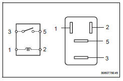
- Inspect no. 1 Fan relay (marking: fan no. 1)
- Remove the relay from the engine room no. 2 Relay block.
- measure the resistance of the relay.
Standard resistance 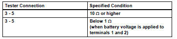
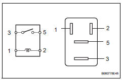
If the result is not as specified, replace the relay.
- Install the relay.
- Inspect no. 2 Fan relay (marking: fan no. 2)
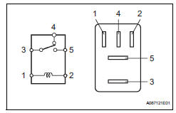
- Remove the relay from the engine room no. 2 Relay block.
- Measure the resistance of the relay.
Standard resistance 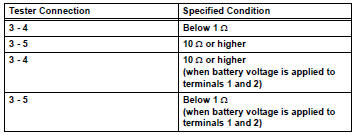
If the result is not as specified, replace the relay.
- Install the relay.
- Inspect no. 3 Fan relay (marking: fan no. 3)
- Remove the relay from the engine room no. 2 Relay block.
- Measure the resistance of the relay.
Standard resistance 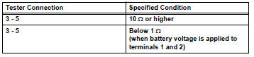
If the result is not as specified, replace the relay.
- Install the relay.
- Install engine room no. 2 Relay block cover
- Connect cable to negative battery terminal
 Cooling fan motor
On-vehicle inspection
Inspect no. 1 Cooling fan motor
Disconnect the no. 1 Fan connector.
Connect the battery and ammeter to the no. 1 Fan
motor connector.
Check th ...
 Radiator
Components
On-vehicle inspection
Check radiator reservoir cap subassembly
Measure the valve opening pressure.
If there are water stains or foreign matter on oring
...
Other materials:
Wireless remote
control/electronic
key battery
Replace the battery with a new one if it is depleted.
You will need the following items:
Flathead screwdriver
Small flathead screwdriver
Lithium battery cr2016 (vehicles without a smart key system), or
cr2032 (vehicles with a smart key system)
Replacing the battery
Vehicles without a ...
Ambient temperature sensor circuit
Description
The ambient temperature sensor is installed in the front part of the
condenser to detect the ambient
temperature and control the air conditioner. The sensor is connected to the
combination meter and
detects fluctuations in the ambient temperature. This data is used for
contr ...
Wireless remote control
Function summary
The wireless remote control can be used to lock and unlock the vehicle.
It also opens and closes the back door.
Vehicles without a smart key system
Locks all the doors
Unlocks all the doors
Pressing the button unlocks the
driver’s door. Pressing the button
again wi ...
