Toyota RAV4 (XA40) 2013-2018 Service Manual: Disassembly
- Remove generator pulley with clutch
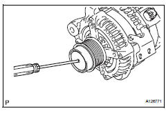
- Remove the cap from the pulley.
- Using a screwdriver, puncture the center of the cap and pry it off.
Notice:
Do not reuse the cap.
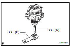
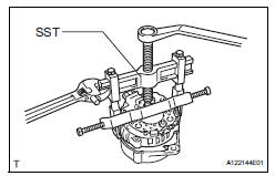
- Install sst to the pulley and vise as shown in the illustration.
Sst 09820-63020
- Mount sst (a) in a vise.
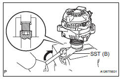
- Turn sst (b) clockwise to loosen the pulley.
- Remove the pulley.
- Remove generator brush holder assembly
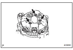
- Remove the 3 nuts and generator rear end cover.
- Remove the terminal insulator.
- Remove the 2 screws and generator brush holder.
- Remove generator rotor assembly
- Remove the bolt and cord clip.
- Remove the 4 bolts.
- Using sst, remove the coil.
Sst 09950-40011 (09951-04020, 09952-04010, 09953-04020, 09954-04010, 09955-04071, 09957-04010)
- Remove the washer.
- Remove the generator rotor.
 Removal
Disconnect cable from negative battery
terminal
Caution:
Wait at least 90 seconds after disconnecting the
cable from the negative (-) battery terminal to
prevent airbag and seat belt preten ...
 Inspection
Inspect generator brush holder assembly
Using a vernier caliper, measure the brush length.
Standard length:
9.5 To 11.5 Mm (0.374 To 0.453 In.)
Minimum length:
4.5 Mm (0.177 In.)
If th ...
Other materials:
Pressure sensor circuit
Description
This dtc is output when the refrigerant pressure is either extremely low
(0.19 Mpa [2.0 Kgf/cm2, 28 psi]
or less) or extremely high (3.14 Mpa [32.0 Kgf/cm2, 455 psi] or more). The air
conditioning pressure
sensor, which is installed on the pipe of the high pressure side, detec ...
Installing child restraints
Follow the child restraint system manufacturer’s instructions.
Firmly secure child restraints to the seats using the latch
anchors or a seat belt. Attach the top tether strap when installing
a child restraint.
The lap/shoulder belt can be used if your child restraint system
is not compati ...
Front wiper rubber
Components
Removal
Remove front wiper blade
Detach the claw as shown in the illustration.
Remove the wiper blade as shown in the illustration.
Notice:
Do not fold the wiper arm with the wiper blade
removed. The arm tip may damage the
windshield surface.
Rem ...
