Toyota RAV4 (XA40) 2013-2018 Service Manual: Ecm power source circuit
Description
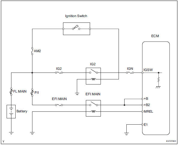
When the ignition switch is turned on, the battery voltage is applied to the igsw of the ecm. The output signal from the mrel terminal of the ecm causes a current to flow to the coil, closing the contacts of the integration relay (efi main relay) and supplying power to either terminal +b or +b2 of the ecm.
Wiring diagram
Inspection procedure
- Inspect fuses (p/i, am2, ig2, efi main, ign)
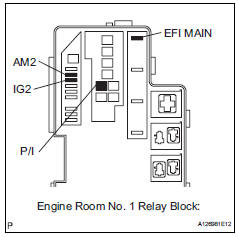
- Remove the p/i fuse, am2 fuse, ig2 fuse and efi main fuse from the engine room no. 1 Relay block.
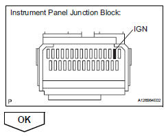
- Remove the ign fuse from the instrument panel junction block.
- Measure the resistance of the fuses.
Standard resistance: below 1

- Reinstall the fuses.
- Inspect relay (ig2, efi main)
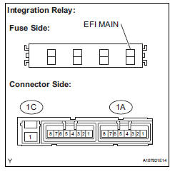
- Remove the integration relay and ig2 relay from the engine room no. 1 Relay block.
- Measure the resistance between the terminal of the integration relay.
Standard resistance 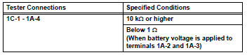
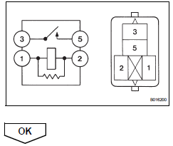
- Measure the resistance between the terminal of the ig2 relay.
Standard resistance 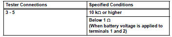
- Reinstall the relay.

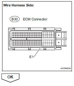
- Check harness and connector (ecm - body ground)
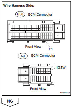
- Disconnect the b30 ecm connector.
- Measure the resistance.
Standard resistance 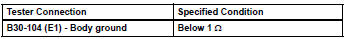
- Reconnect the ecm connector.
- Inspect ecm (igsw voltage)
- Disconnect the b30 and a9 ecm connectors.
- Turn the ignition switch on.
- Measure the voltage between the terminals of the b30 and a9 ecm connectors.
Standard voltage 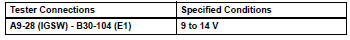
- Reconnect the ecm connector.

- Check harness and connector (relay block - ecm, ignition switch, battery)
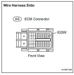
- Disconnect the a9 ecm connector.
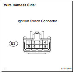
- Disconnect the e3 ignition switch connector.
- Disconnect the battery positive terminal.
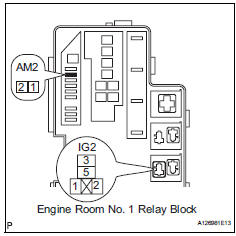
- Remove the am2 fuse and ig2 relay.
- Measure the resistance between the terminals.
Standard resistance (check for open)
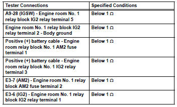
Standard resistance (check for short)
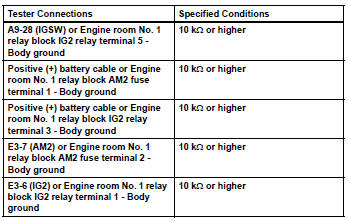
- Reinstall the relay and fuse.
- Reconnect the connectors.

- Inspect ignition switch (see page es-261)

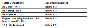
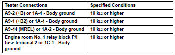
- Check harness and connector (integration relay - ecm, battery, body ground)
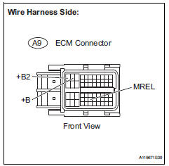
- Disconnect the a9 ecm connector.
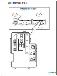
- Remove the integration relay from the engine room no. 1 Relay block.
- Disconnect the integration relay connector.
- Remove the p/i fuse from the engine room no. 1 Relay block.
- Check the resistance between the terminals.
Standard resistance (check for open)
Standard resistance (check for short)
- Reconnect the connectors.
- Reinstall the integration relay and p/i fuse.
 Evap system
Related dtcs
If any evap system dtcs are set, the malfunctioning area can be determined
using the table below.
Notice:
If the reference pressure difference between the first and second ch ...
 Vc output circuit
Description
The ecm constantly generates 5 v power from the battery voltages supplied to
the +b (batt) terminal to
operate the microprocessor. The ecm also provides this power to the sensors
thr ...
Other materials:
Rear view monitor
system
The rear view monitor system assists the driver by displaying an
image of the view behind the vehicle and fixation guide lines
while backing up, for example while parking.
The screen illustrations used in this text are intended as examples,
and may differ from the image that is actually displaye ...
Cleaning and protecting the vehicle interior
Perform cleaning in a manner
appropriate to each
component and its material.
Protecting the vehicle
interior
Remove dirt and dust using a
vacuum cleaner. Wipe dirty
surfaces with a cloth dampened
with lukewarm water.
If dirt cannot be removed,
wipe it off with a soft cloth
dampened with neut ...
Window lock switch
Press the switch to lock the passenger
window switches.
Use this switch to prevent children
from accidentally opening or closing
a passenger window.
The power windows can be operated when
Vehicles without a smart key system
The engine switch is in the “on” position.
Vehicles ...
