Toyota RAV4 (XA40) 2013-2018 Service Manual: Engine immobiliser system malfunction
![]()
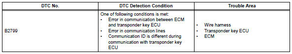
Description
This dtc is output when one of the following occurs: 1) the ecm detects errors in its own communications with the transponder key ecu; 2) the ecm detects errors in the communication lines; or 3) the ecu communication id between the transponder key ecu and ecm is different and an engine start is attempted. Before troubleshooting for this dtc, make sure no transponder key ecu dtcs are present. If present, troubleshoot the transponder key ecu dtcs first.
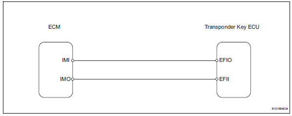
Wiring diagram
Inspection procedure
- Check for dtc
- Delete the dtc (see page ei-18).
- Recheck for dtc.
Ok: b2799 output does not reoccur.

- Check wire harness (transponder key ecu - ecm)
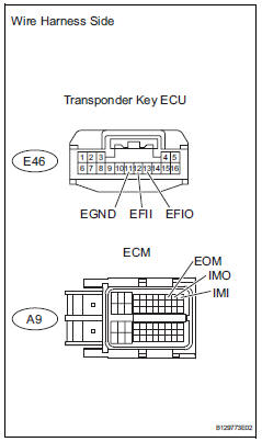
- Disconnect the e46 ecu connector.
- Disconnect the a9 ecm connector.
- Measure the resistance of the wire harness side connectors.
Standard resistance 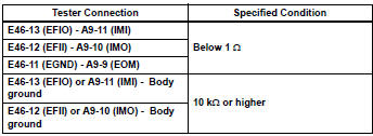

- Check transponder key ecu (operation)
- Temporarily replace the transponder key ecu with a new or normally functioning one.
- Check that then engine starts normally.
Ok: engine starts normally.

End (transponder key ecu is defective)
 Communication malfunction no. 1
Description
This dtc is output when a communication error occurs between the transponder
key amplifier and
transponder key ecu. Some possible reasons for the communication error are: 1) 2
or ...
 Security indicator light circuit
Description
When the transponder key is registered, the transponder key ecu indicates the
key registration condition
by lighting up, blinking or turning off the security indicator.
Wiring diagram ...
Other materials:
Trailer towing
Your vehicle is designed
primarily as a passenger-and-
load-carrying vehicle.
Towing a trailer can have an
adverse impact on handling,
performance, braking, durability,
and fuel consumption.
For your safety and the
safety of others, you must
not overload your vehicle or
trailer. You must also
ensu ...
Front speed sensor
Components
Removal
Hint:
Use the same procedures for the lh side and rh side.
The procedures listed below are for the lh side.
Disconnect cable from negative battery
terminal
Caution:
Wait at least 90 seconds after disconnecting the
cable from the negative (-) battery termin ...
Parking brake
Sets the parking brake
Fully pull the parking brake while
depressing the brake pedal.
Releases the parking brake
Slightly raise the lever and lower it
completely while pressing the button.
Usage in winter time
Notice
Before driving
Fully release the parking brake.
Driving t ...
