Toyota RAV4 (XA40) 2013-2018 Service Manual: Diagnosis system
- Description
- Engine immobiliser system data and diagnostic trouble codes (dtcs) can be read through the vehicle's data link connector 3 (dlc3). In some cases, a malfunction may be occurring in the engine immobiliser system even though the security indicator light is not illuminated. When the system seems to be malfunctioning, use the intelligent tester to check for malfunctions and perform repairs.
- Check dlc3
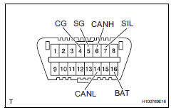
The vehicle's ecu uses the iso 15765-4 communication protocol. The terminal arrangement of the dlc3 complies with sae j1962 and matches the iso 15765-4 format.
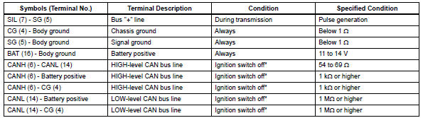
Notice:
*: Before measuring the resistance, leave the vehicle as is for at least 1 minute and do not operate the ignition switch, other switches or doors.
If the result is not as specified, the dlc3 may have a malfunction. Repair or replace the harness and connector.
Hint:
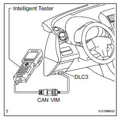
Connect the cable of the intelligent tester (with can vim) to the dlc3, turn the ignition switch on and attempt to use the intelligent tester. If the screen displays unable to connect to vehicle, a problem exists in the vehicle side or the tester side.
If the communication is normal when the tester is connected to another vehicle, inspect the dlc3 on the original vehicle.
If the communication is still not possible when the tester is connected to another vehicle, the problem is probably in the tester itself. Consult the service department listed in the tester's instruction manual.
 Terminals of ecu
Check transponder key amplifier
Disconnect the e5 amplifier connector.
Measure the resistance of the wire harness side
connector.
If the result is not as specified, there may b ...
 Dtc check / clear
Check dtc
Connect the intelligent tester (with can vim) to the
dlc3.
Turn the ignition switch on and turn the intelligent
tester on.
Select the following menu items: diagnosis /
...
Other materials:
Voice command system
The voice command system enables the hands-free system to
be operated using voice commands.
Using the voice command system
Press the talk switch.
To cancel the voice command system,
press and hold the talk switch.
After a beep sounds, say the desired command.
On the list screen, ...
Condenser
Components
On-vehicle inspection
Inspect cooler condenser assembly
If the fins of the cooler condenser are dirty, clean
them with water. Dry the fins with compressed air.
Notice:
Do not damage the fins of the condenser.
If a fin of the cooler condenser is bent, straighte ...
Automatic
air conditioning system
Air outlets and fan speed are automatically adjusted according
to the temperature setting.
DriverŌĆÖs side temperature control
dial
Automatic mode button
Micro dust and pollen filter
mode button
DriverŌĆÖs side temperature setting
display
Fan speed display
Air outlet display ...
