Toyota RAV4 (XA40) 2013-2018 Service Manual: Evaporative emission system reference orifice
Dtc summary
Hint:
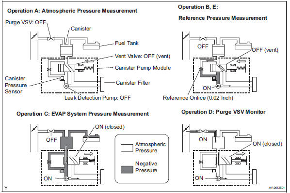
The reference orifice is located inside the canister pump module.
Description
The description can be found in the evap (evaporative emission) system (see page es-335).
Inspection procedure
Refer to the evap system (see page es-340).
Monitor description
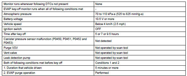
5 Hours* after the ignition switch is turned off, the leak detection pump creates negative pressure (vacuum) in the evap system. The ecm monitors for leaks and actuator malfunctions based on the evap pressure.
Hint:
*: If the engine coolant temperature is not below 35°c (95°f) 5 hours after the ignition switch is turned off, the monitor check starts 2 hours later. If it is still not below 35°c (95°f) 7 hours after the ignition switch is turned off, the monitor check starts 2.5 Hours later.

*: If only a small amount of fuel is in the fuel tank, it takes longer for the evap pressure to stabilize.
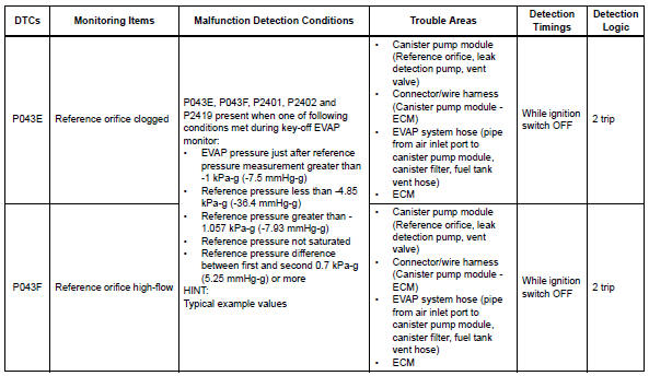
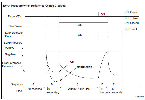
- P043e: reference orifice clogged
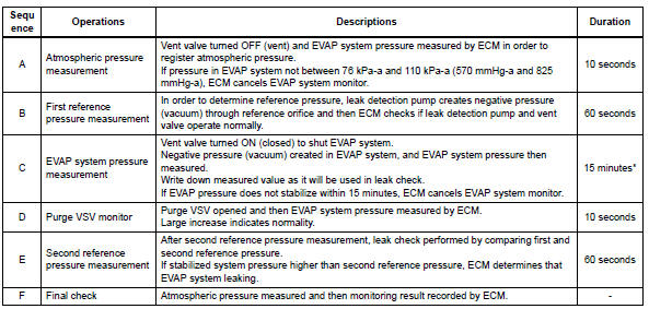
In operation b, the leak detection pump creates negative pressure (vacuum) through the reference orifice.
The evap system pressure is then measured by the ecm, using the canister pressure sensor, to determine the reference pressure. If the pressure is lower than -4.85 Kpa-g (-36.4 Mmhg-g), the ecm interprets this as a clog malfunction in the reference orifice, and stops the evap system monitor.
The ecm then illuminates the mil and sets the dtc (2 trip detection logic).
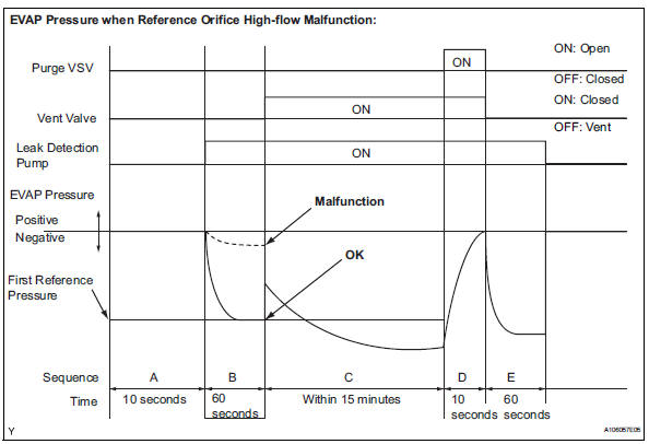
- P043f: reference orifice high-flow
In operation b, the leak detection pump creates negative pressure (vacuum) through the reference orifice.
The evap system pressure is then measured by the ecm using the canister pressure sensor to determine the reference pressure. If the pressure is higher than -1.057 Kpa-g (-7.93 Mmhg-g), the ecm interprets this as a high-flow malfunction in the reference orifice, and stops the evap system monitor. The ecm then illuminates the mil and sets the dtc (2 trip detection logic).
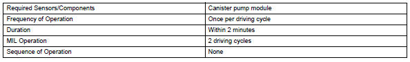
Monitor strategy
Typical enabling conditions
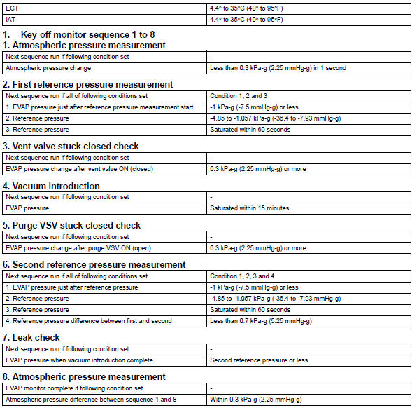
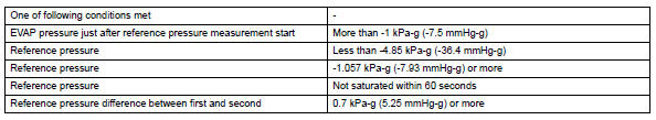
Typical malfunction thresholds
"Saturated" indicates that the evap pressure change is less than 0.286 Kpa-g (2.14 Mmhg-g) in 60 seconds.
Monitor result
Refer to checking monitor status (see page es-17).
 Catalyst system efficiency below threshold (bank 1)
Monitor description
The ecm uses sensors mounted in front of and behind the three-way catalytic
converter (twc) to
monitor its efficiency.
The first sensor, the air-fuel ratio (a/f) sensor, ...
 Evaporative emission control system incorrect purge flow
Dtc summary
Description
The description can be found in the evap (evaporative emission) system (see
page es-335).
Inspection procedure
Refer to the evap system (see page es-340).
Monito ...
Other materials:
Air conditioning amplifier communication stop mode
Description
Wiring diagram
Inspection procedure
Notice:
Turn the ignition switch off before measuring the resistances
of the main wire and the branch
wire.
After the ignition switch is turned off, check that the key
reminder warning system and light
reminder warning sy ...
Customizing the startup and screen off images (if equipped)
An image can be copied from a usb memory and used as the startup
and screen off images.
When the engine switch is in the “acc” or “on” position (vehicles
without a smart key system) or accessory or ignition on mode
(vehicles with a smart key system), the initial screen will be displaye ...
Fuel pressure regulator
Components
Removal
Remove fuel tank assembly
Remove the fuel tank (see page fu-39).
Remove fuel tank main tube sub-assembly
Remove the joint clip and fuel tank main tube.
Caution:
Before removing the tube joint clip, check for
foreign matter around the cli ...
