Toyota RAV4 (XA40) 2013-2018 Service Manual: Front wiper rubber
Components
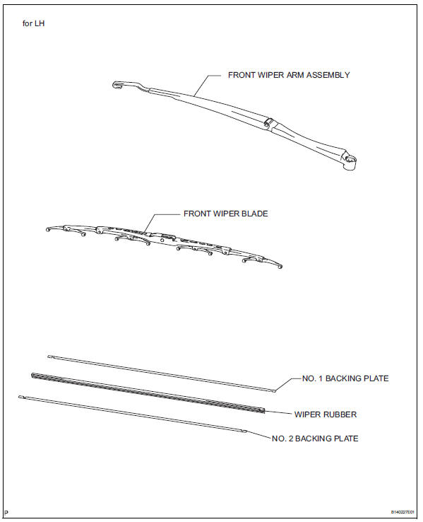
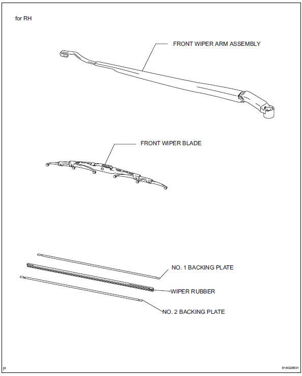
Removal
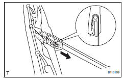
- Remove front wiper blade
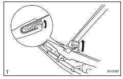
- Detach the claw as shown in the illustration.
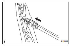
- Remove the wiper blade as shown in the illustration.
Notice:
Do not fold the wiper arm with the wiper blade removed. The arm tip may damage the windshield surface.
- Remove wiper rubber
- Detach the head part (large side) of the wiper rubber from the wiper blade.
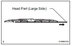
- Remove the wiper rubber in the direction indicated by the arrow in the illustration.
Notice:
Do not pull out the wiper rubber forcibly. Doing so will deform the backing plate or damage the blade claw.
- Remove the 2 wiper rubber backing plates from the wiper rubber.
Installation
- Install wiper rubber
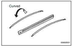
- Install the 2 packing plates to the rubber.
Notice:
Install the packing plates facing the proper direction.
- Install the wiper rubber to the claw of the wiper blade in the direction indicated by the arrow in the illustration.
Hint:
Install the wiper rubber so that the head part (large side) of the wiper rubber faces the arm axle side.
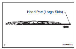
- Attach the head part (large side) of the wiper rubber to the rear end side claw of the wiper blade.
Notice:
Push the wiper blade into the grooves of the wiper rubber to attach them completely.
- Install front wiper blade
- Attach the claw to install the wiper blade.
 Front wiper motor and link
Components
Removal
Disconnect cable from negative battery
terminal
Caution:
Wait at least 90 seconds after disconnecting the
cable from the negative (-) battery terminal to
prevent ai ...
 Rear wiper motor
Components
Removal
Disconnect cable from negative battery
terminal
Caution:
Wait at least 90 seconds after disconnecting the
cable from the negative (-) battery terminal to
prevent ai ...
Other materials:
Sruepsptrleaminetnstal restraint system center airbag sensor assembly
Components
On-vehicle inspection
Check center airbag sensor assembly
(vehicle not involved in collision and
airbag not deployed)
Perform a diagnostic system check (see page rs-
49).
Check center airbag sensor assembly
(vehicle involved in collision and airbag
not deplo ...
Diaphragm oil seal
Components
Removal
Drain differential oil
Using a 10 mm socket hexagon wrench, remove the
rear differential drain plug and gasket, and drain the
oil.
Install a new gasket to the rear differential drain
plug.
Using a 10 mm socket hexagon wrench, install the
rear differe ...
Installation
Hint:
Use the same procedures for the rh side and lh side.
The procedures listed below are for the lh side.
Install rear stabilizer bush
Install the 2 bushes.
Hint:
Install each bush to the outer side of the bush
stopper on each stabilizer bar.
Install each bush with ...
