Toyota RAV4 (XA40) 2013-2018 Service Manual: Exhaust pipe
Installation
- Install front exhaust pipe assembly
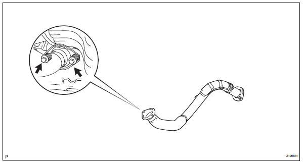
- Using a vernier caliper, measure the free length of the compression spring.
Minimum length: 41.5 Mm (1.634 In.)
If the length is less than the minimum, replace the compression spring.
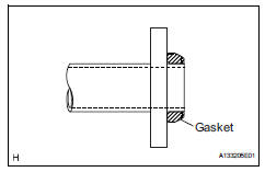
- Install a new gasket by hand so that its surface is flush with the exhaust manifold.
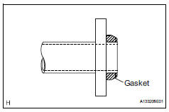
Notice:
- Make sure the gasket is facing the correct direction.
- Do not reuse the removed gasket.
- Do not push in the gasket while installing the front exhaust pipe.
- Install the front exhaust pipe with the 2 compression springs and 2 bolts.
Torque: 43 n*m (438 kgf*cm, 32 ft.*Lbf)
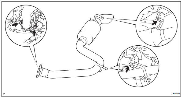
- Install center exhaust pipe assembly
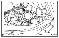
- Install a new gasket onto the front exhaust pipe.
- Connect the 3 exhaust pipe supports, and install the center exhaust pipe.
- Install the 2 bolts.
Torque: 43 n*m (438 kgf*cm, 32 ft.*Lbf)
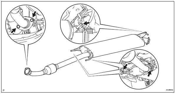
- Install tailpipe assembly
- Using a vernier caliper, measure the free length of the compression spring.
Minimum length: 38.5 Mm (1.516 In.)
If the length is less than the minimum, replace the compression spring.
- Install a new gasket by hand so that its surface is flush with the center exhaust pipe.
Notice:
- Make sure the gasket is facing the correct direction.
- Do not reuse the removed gasket.
- Do not push in the gasket while installing the tailpipe.
- Connect the 2 exhaust pipe supports, and install the tailpipe.
- Install the 2 compression springs and 2 bolts.
Torque: 43 n*m (438 kgf*cm, 32 ft.*Lbf)
- Install heated oxygen sensor (for bank 1 sensor 2) (see page ec-24)
- Connect cable to negative battery terminal
- Check for exhaust gas leaks
If gas is leaking, tighten the areas necessary to stop the leak. Replace damaged parts as necessary.
 2az-fe exhaust
...
 Exhaust pipe
Components
Removal
Disconnect cable from negative battery terminal
Caution:
Wait at least 90 seconds after disconnecting the
cable from the negative (-) battery terminal to
prevent airb ...
Other materials:
Engine (ignition) switch
(vehicles without smart
key system)
Starting the engine
1. Pull the parking brake switch
to check that the parking
brake is set.
The parking brake indicator will
come on.
2. Check that the shift lever is
set in P.
3. Firmly depress the brake
pedal.
4. Turn the engine switch to
START to start the engine.
â– If the engine does not s ...
Short in driver side squib circuit
Description
The driver side squib circuit consists of the center airbag sensor, the
spiral cable and the steering pad.
The circuit instructs the srs to deploy when the deployment conditions are met.
These dtcs are recorded when a malfunction is detected in the driver side squib
circui ...
Vehicle speed sensor "A"
description
The speed sensor detects the wheel speed and sends the appropriate signals to
the skid control ecu.
The skid control ecu converts these wheel speed signals into a 4-pulse signal
and outputs it to the ecm
via the combination meter. The ecm determines the vehicle speed based o ...
