Toyota RAV4 (XA40) 2013-2018 Service Manual: Fuel pump control circuit
Description
When the engine is cranked, the starter relay drive signal output from the star terminal of the ecm is input into the sta terminal of the ecm, and ne signal generated by the crankshaft position sensor is also input into the ne+ terminal. Thus, the ecm interprets that the engine is cranked, and turns the transistor tr1 in the ecm internal circuit on. The current flows to the c/opn (circuit opening) relay by turning the tr1 on. Then, the fuel pump operates.
While the ne signal is input into the ecm, when the engine is running, the ecm turns the tr1 on continuously.
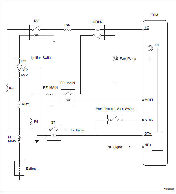
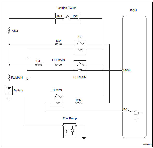
Wiring diagram
Inspection procedure
- Perform active test using intelligent tester (fuel pump/spd)
- Connect the intelligent tester to the dlc3.
- Turn the ignition switch on and turn the tester on.
- Select the following menu items: diagnosis / enhanced obd ii / active test / fuel pump / spd.
- Check whether the fuel pump operating sound occurs when performing the active test on the tester.
Ok: fuel pump operating sound occurs.

- Inspect instrument panel junction block assembly (c/opn relay input voltage)
- Measure the voltage between the terminal of the instrument panel junction block (j/b) and the body ground when the ignition switch is turned on and off.
Standard voltage 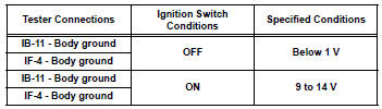
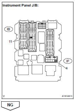
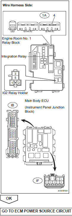
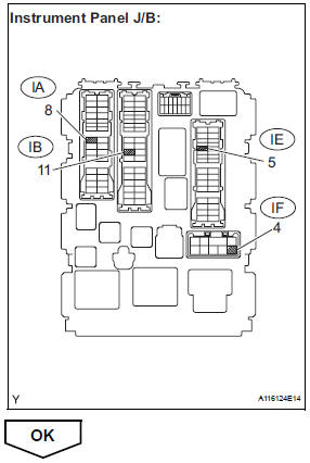
- Check harness and connector (instrument panel j/b - integration relay, ig2 relay)
- Remove the integration relay and ig2 relay from the engine room no. 1 Relay block.
- Disconnect the instrument panel junction block connector.
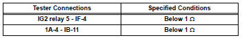
- Check the resistance.
Standard resistance (check for open)
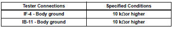
Standard resistance (check for short)
- Reinstall the integration relay and ig2 relay.
- Reconnect the instrument panel junction block connector.

- Inspect instrument panel junc.ssembly (c/opn relay)
- Remove the instrument panel junction block.
- Measure the c/opn relay resistance.
Standard resistance 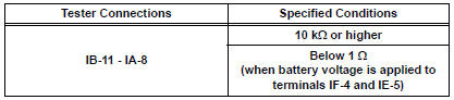
Hint:
Relay coil circuit between if-4 and ie-5 is not through ign fuse.
- Reinstall the instrument panel junction block.
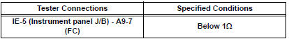
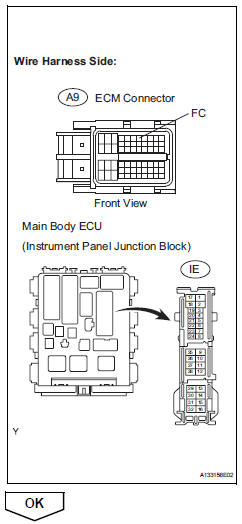
- Check harness and connector (instrument panel j/b - ecm)
- Disconnect the a9 ecm connector.
- Disconnect the ie connector from instrument panel junction block.
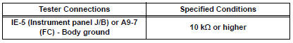
- Measure the resistance.
Standard resistance (check for open)
Standard resistance (check for short)
- Reconnect the instrument panel junction block and the ecm connectors.
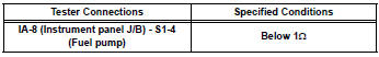
- Check harness and connector (c/opn relay - fuel pump - body ground)
- Check the harness and the connectors between the instrument panel junction block assembly and the fuel pump.
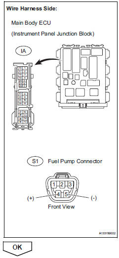
- Disconnect the ia instrument panel junction block connector.
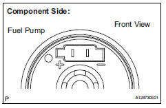
- Disconnect the s1 fuel pump connector.
- Measure the resistance.
Standard resistance (check for open)
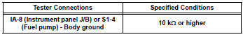
Standard resistance (check for short)
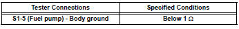
- Check the harness and the connectors between the fuel pump and the body ground.
- Disconnect the s1 fuel pump connector.
- Measure the resistance.
Standard resistance (check for open)
- Reconnect the instrument panel junction block connector
- Reconnect the fuel pump connector.
- Inspect fuel pump
- Inspect fuel pump resistance.
- Measure the resistance between the terminals.
Standard resistance: 0.2 To 3.0 ٠at 20°c(68°f)
- Inspect fuel pump operation.
- Apply the battery voltage to both the terminals.
Notice:
- These tests must be done quickly (within 10 seconds) to prevent the coil from burning out.
- Keep the fuel pump as far away from the battery as possible.
- Always turn the voltage on and off on the battery side, not the fuel pump side.
- Read value using intelligent tester (starter sig)
- Connect the intelligent tester to the dlc3.
- Turn the ignition switch on and turn the tester on.
- Select the following menu items: diagnosis / enhanced obd ii / data list / primary / starter sig.
- Check the result when the ignition switch is turned to on and start.
Ok 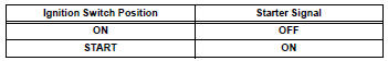

- Read value using intelligent tester (engine spd)
- Connect the intelligent tester to the dlc3.
- Turn the ignition switch on and turn the tester on.
- Select the following menu items: diagnosis / enhanced obd ii / data list / primary / engine spd.
- Read the values displayed on the tester while cranking.
Standard: values are displayed continuously.
 Vc output circuit
Description
The ecm constantly generates 5 v power from the battery voltages supplied to
the +b (batt) terminal to
operate the microprocessor. The ecm also provides this power to the sensors
thr ...
 Mil circuit
Description
The mil (malfunction indicator lamp) is used to indicate vehicle malfunction
detections by the ecm.
When the ignition switch is turned on, power is supplied to the mil circuit, and
...
Other materials:
Front seat frame with adjuster
Inspection
Inspect front seat frame with adjuster
Check operation of the seat frame (slide motor).
Check if the seat frame moves smoothly when
the battery is connected to the slide motor
connector terminals.
Ok
If the result is not as specified, replace the seat
frame w ...
Brk relay
On-vehicle inspection
Inspect brk relay
Remove the brk relay from the engine room no. 1
Relay block.
Measure the resistance of the relay.
Standard resistance
If the result is not as specified, replace the relay. ...
Precaution
Notice:
Perform the reset memory procedures (a/t
initialization) when replacing the automatic transaxle
assembly, engine assembly or ecm (see page ax-18).
Hint:
Reset memory cannot be completed by only reconnecting
the cable to the negative (-) battery terminal.
Caution:
When using compresse ...
