Toyota RAV4 (XA40) 2013-2018 Service Manual: Ig power source circuit
Description
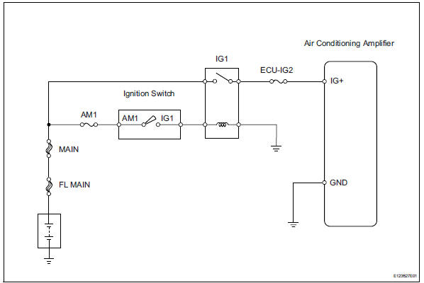
This is the main power source supplied to the air conditioning amplifier when the ignition switch is on (ig). This power source is used for operating components, such as the air conditioning amplifier and servo motors.
Wiring diagram
Inspection procedure
- Inspect fuse (ecu-ig2)
- Remove the ecu-ig2 fuse from the instrument panel junction block.
- Measure the resistance of the fuse.
Standard resistance:
below 1 


- Check wire harness (air conditioning amplifier - battery)
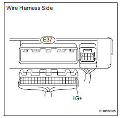
- Disconnect the e37 amplifier connector.
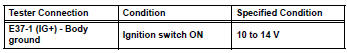
- Measure the voltage of the wire harness side connector.
Standard voltage

- Check wire harness (air conditioning amplifier - body ground)
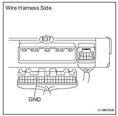
- Disconnect the e37 amplifier connector.
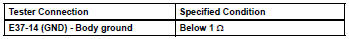
- Measure the resistance of the wire harness side connector.
Standard resistance

Proceed to next circuit inspection shown in problem symptoms table
 Compressor circuit
Description
When the a/c switch is turned on, the magnetic clutch on signal is sent from
the air conditioning
amplifier. Then the mg clt relay turns on to operate the magnetic clutch.
Wiring diag ...
 Back-up power source circuit
Description
This is the back-up power source circuit for the air conditioning amplifier.
Power is supplied even when the
ignition switch is turned off and is used for functions such as the diagnos ...
Other materials:
Throttle / pedal position sensor
Hint:
These dtcs relate to the accelerator pedal position (app) sensor.
Description
Hint:
This etcs (electronic throttle control system) does not use a throttle cable.
The app sensor is mounted on the accelerator pedal bracket and has 2 sensor
circuits: vpa (main) and
vpa2 (sub). This ...
Voice settings
This screen is used for setting the voice command guidance
system.
Adjust the voice guidance volume
setting.
Set the voice recognition
prompts “high”, “low” or “off”.
Train voice recognition
Set the voice prompt interrupt
on/off.
Voice recognition tutorial
To re ...
Reassembly
Caution:
Wear protective gloves. Sharp areas on the seat frame
(with adjuster) may injure your hands.
Hint:
Use the same procedures for the rh side and lh side.
The procedures listed below are for the lh side.
Install occupant classification ecu (for
driver side) (see page rs-394)
...
