
Toyota RAV4 (XA40) 2013-2018 Service Manual: Ignition key cylinder light
Components
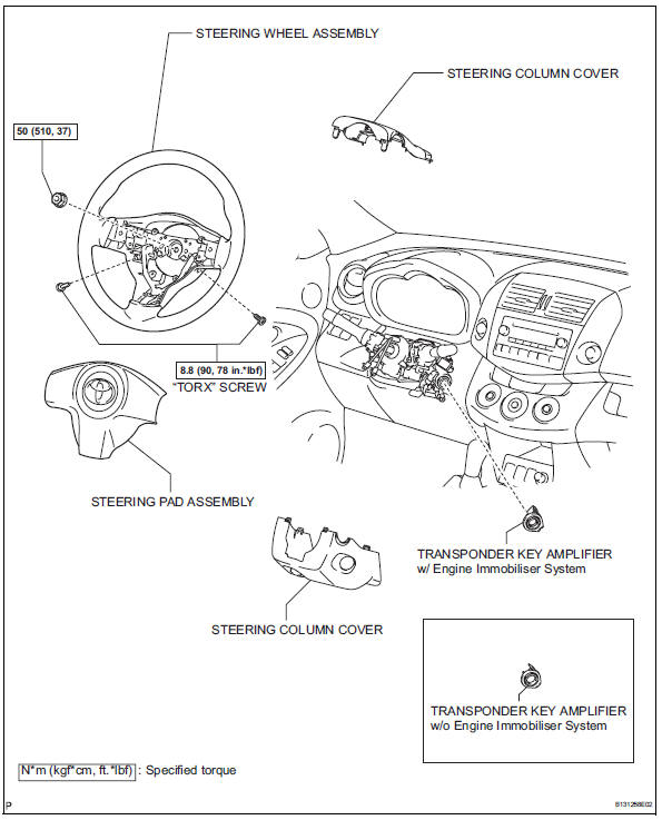
Removal
- Disconnect cable from negative battery
Caution:
Wait at least 90 seconds after disconnecting the cable from the negative (-) battery terminal to prevent airbag and seat belt pretensioner activation.
- Place front wheels facing straight ahead
- Remove steering pad assembly (see page rs- 336)
- Remove steering wheel assembly (see page sr-12)
- Remove steering column cover (see page sr-12)
- Remove transponder key amplifier (see page sr-14)
Inspection
- Inspect transponder key amplifier
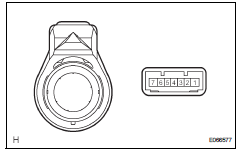
- W/ engine immobiliser system:
Connect the battery's positive (+) lead to terminal 2 and the negative (-) lead to terminal 6, and then check that the light comes on.
Ok: led illuminates.
If the result is not as specified, replace the transponder key amplifier.
- W/o engine immobiliser system:
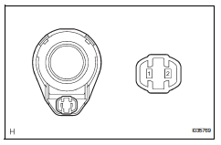
- Connect the battery's positive (+) lead to terminal 2 and the negative (-) lead to terminal 1, and then check that the light comes on.
Ok: led illuminates.
If the result is not as specified, replace the transponder key amplifier.
Installation
- Install transponder key amplifier (see page sr-18)
- Install steering column cover (see page sr- 20)
- Install steering wheel assembly (see page sr-21)
- Place front wheels facing straight ahead
- Inspect steering wheel center point
- Install steering pad assembly (see page rs- 336)
- Connect cable to negative battery terminal
- Inspect steering pad assembly (see page rs- 337)
- Check srs warning light
- Check the srs warning light (see page rs-337).
 Luggage room light
Components
Removal
Disconnect cable from negative battery
terminal
Caution:
Wait at least 90 seconds after disconnecting the
cable from the negative (-) battery terminal to
prevent ai ...
 Vanity light
Components
Removal
Hint:
Use the same procedures for the rh and lh sides.
The procedures listed below are for the lh side.
Disconnect cable from negative battery
terminal
Cautio ...
Other materials:
Fuel Economy
Current fuel economy
Displays the driving range with
remaining fuel.
Average fuel economy
Displays the average fuel economy
since the function was reset or the average fuel economy after starting.* 1,
2, 3
The average fuel economy selected
by "Fuel Economy" on the
screen is displayed.
*1 ...
Engine (ignition) switch
(vehicles without a
smart key system)
Starting the engine
Check that the parking brake is set.
Check that the shift lever is set in p.
Firmly depress the brake pedal.
Turn the engine switch to the “start� position to start the engine.
Changing the engine switch positions
“Lock�
The steering wheel is locked an ...
Switches
Driving position memory switches*1
Window lock switch
Power window switches
Door lock switches
Outside rear view mirror switches
"ODO TRIP" switch (vehicles with 7-inch multi-information display)
"ODO TRIP" switch (vehicles with 12.3-inch multi-information
display)
Instrument panel light ...
